Page 15
15628-0-0903
VENTING FIREPLACE
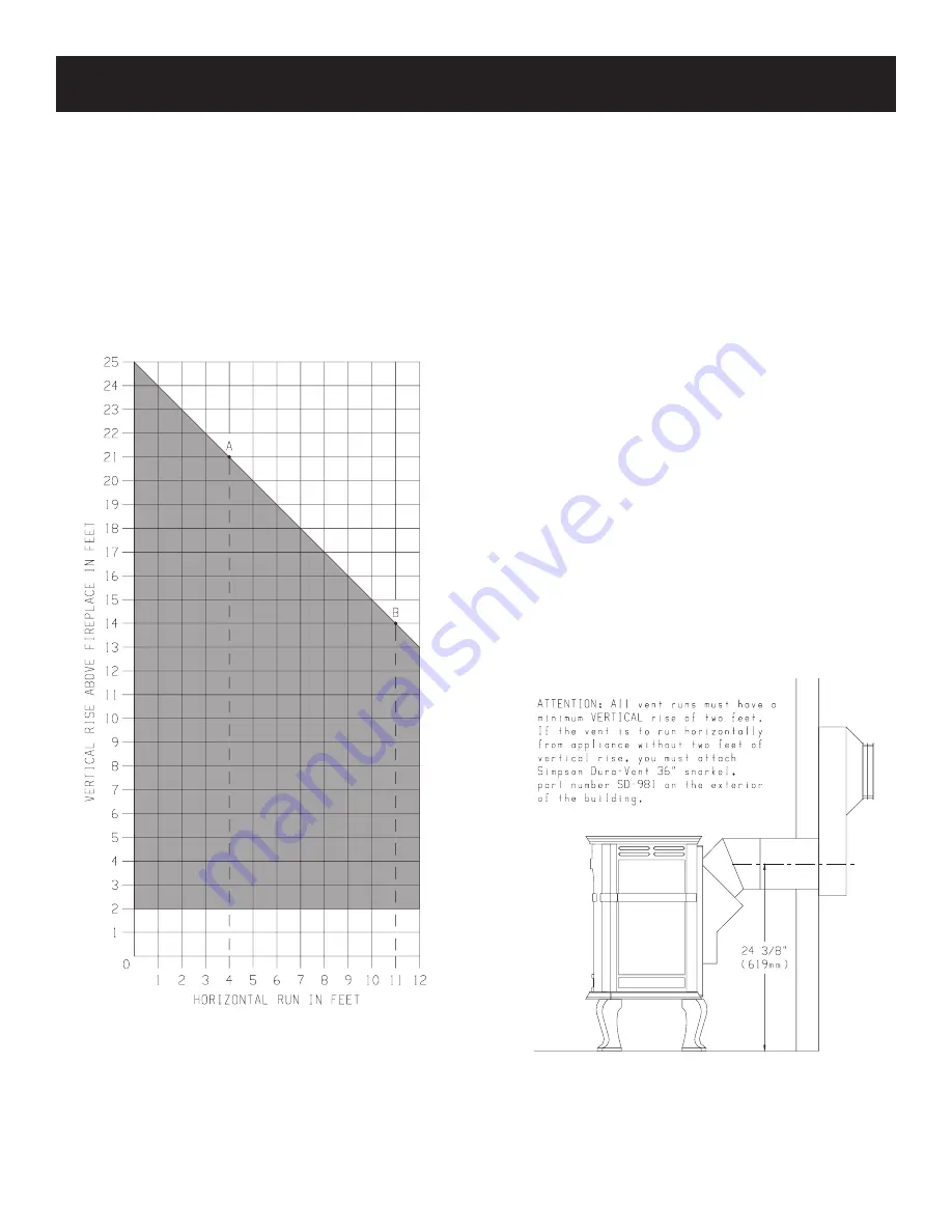
Venting Graph (Dimensions in Feet) (Figure 16)
1. Determine the height of the center of the termination. Using
this dimension on the Venting Graph, locate the point it
intersects with the slanted graph line, or the right edge of the
graph.
2. From the point of this intersection, draw a vertical line to the
bottom of the graph.
3. Adjust the indicated maximum dimension for additional elbows
if necessary.
4. Position the unit so that maximum horizontal run is not
exceeded.
Venting Must Be Within Shaded Area
Figure 16
Venting Requirements (Figure 17)
Minimum vertical rise from appliance outlet = 24 inches (610mm).
Attention: All vent runs must have a minimum VERTICAL
rise of two feet. If the vent run is directly behind the appliance,
you must attach Simpson Dura-Vent 36" snorkel, part number
SD-981 on the exterior of the building.
Maximum vertical rise from appliance outlet = 25 feet (7.62m),
the restrictor plate may be used above 10 feet.
Maximum horizontal run from appliance outlet = 12 feet (3.66m).
Maximum vertical rise and horizontal run is a combined total of 25
feet (7.62m).
Maximum elbows = (2) 90
°
, for the second elbow subtract 5 feet
from a horizontal run.
To Use the Vent Graph
EXAMPLE A:
If the vertical rise from the appliance outlet is 21 feet, the
horizontal run to the outer wall flange of the vent termination must
not exceed 4 feet with (1) 90
°
elbow.
EXAMPLE B:
If the vertical rise from the appliance outlet is 14 feet, the
horizontal run to the outer wall flange of the vent tremination must
not exceed 11 feet with (1) 90
°
elbow.
SPECIAL NOTE: For each 45 degree elbow installed in the
horizontal run, the length of the horizontal run MUST be reduced
by 18 inches (45cm). This does not apply if the 45 degree elbows
are installed on the vertical rise of the vent system.
Example: According to the chart the maximum horizontal run is
12 feet and if two 45 degree elbows are required in the horizontal
run it must be reduced to 9 feet.
The maximum number of 45 degree elbows permitted per side
wall installation is two. These elbows can be installed in either the
vertical rise or horizontal run.
Figure 17
Содержание Classic CIDV-30-20
Страница 33: ...Page 33 15628 0 0903 19 29 30 PARTS VIEW FOR CIDV 30 20 ...
Страница 35: ...Page 35 15628 0 0903 PARTS VIEW FOR STOVE CASTING Models CIFB 1 CIPB 1 CIPG 1 CIPS 1 CIPN 1 CIPR 1 ...
Страница 38: ...Page 38 15628 0 0903 SERVICE NOTES ...
Страница 39: ...Page 39 15628 0 0903 SERVICE NOTES ...


