background image

22992-0-1106

Page 12

OPTIONAL SINGLE SPEED BLOWER INSTALLATION INSTRUCTIONS

Attention:

  Install blower assembly before connecting gas inlet 

supply line.

Wiring

The appliance, when installed, must be electrically grounded in 

accordance  with  local  codes  or,  in  the  absence  of  local  codes, 

with  the

  National  Electrical  Code, ANSI/NFPA  70

,  if  an  exter-

nal electrical source is utilized. 

This appliance is equipped with 

a  three-prong  [grounding]  plug  for  your  protection  against 

shock hazard and should be plugged directly into a properly 

grounded three-prong receptacle. Do not cut or remove the 

grounding prong from this plug. 

For an ungrounded receptacle, 

an adapter, which has two prongs and a wire for grounding, can 

be purchased, plugged into the ungrounded receptacle and its wire 

connected to the receptacle mounting screw. With this wire com-

pleting the ground, the appliance cord plug can be plugged into 

the adapter and be electrically grounded.

Caution: 

Label all wires prior to disconnection when servic-

ing controls. Wiring errors can cause improper and dangerous 

operation. Verify proper operation after servicing.

Note:

 Junction box on right side of firebox must be pre-wired at 

time of firebox installation for use with blower assembly. A 

standard wall ON/OFF wall switch or optional SCV1 Vari-

able Speed Control Kit should be installed to activate pow-

er to the Firebox, and control the operation of the FBB5 

Blower assembly. It is recommended that installation of the 

wiring be performed by a qualified electrician. 

See Figure 

25.

1.  If installed, turn OFF gas supply to firebox/gas log.

2.  If applicable, turn OFF electric supply to firebox.


CAUTION:

  ALL  WIRING  SHOULD  BE  DONE  BY 

A  QUALIFIED  ELECTRICIAN  AND  SHALL  BE  IN 

COMPLIANCE  WITH ALL  LOCAL,  CITY AND  STATE 

BUILDING CODES. BEFORE MAKING THE ELECTRI-

CAL CONNECTION, MAKE SURE THAT MAIN POWER 

SUPPLY IS DISCONNECTED. THE APPLIANCE, WHEN 

INSTALLED,  MUST  BE  ELECTRICALLY  GROUNDED 

IN ACCORDANCE  WITH  LOCAL  CODES,  WITH  THE 

NATIONAL  ELECTRICAL  CODE ANSI/NFPA  70  (LAT-

EST EDITION).

A factory installed junction box is located on the lower right 

side of the firebox. Wiring must be fed to the junction box 

and  attached  to  the  receptacle  that  is  provided.  From  right 

side of the firebox, remove the screw securing the junction 

box assembly. Leave approximately 6” of wire in the junction 

box for connection.
Attach black wire to one side of the receptacle and white wire 

to opposite side of receptacle. The ground wire should be at-

tached to the green (ground) screw.
Install  the  recepticle  into  the  junction  box.  Attach  cover 

plate.

Attention:

 If installed, do not damage gas inlet supply line 

when blower assembly is inserted into firebox. In some cases, 

removal the gas inlet supply line may be necessary. 

3.  Determine which type of firebox you have prior to installa-

tion. 

See Figures 26 and 27

.

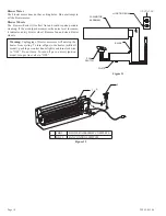
Figure 25

REMOVE BOTTOM LOUVER TO

INSTALL BLOWER ASSEMBLY

Figure 26

REMOVE COVER PLATE TO

INSTALL BLOWER ASSEMBLY

Figure 27

Deluxe Louvered 

Models

Deluxe Flush Face 

Models

Содержание VFD32FB0F-1

Страница 1: ...Refer to this manual For assistance or additional in formation consult a qualified installer service agency or the gas supplier Carefully review the instructions supplied with the decora tive type unvented room heater for the minimum fireplace size requirement DO NOT INSTALL A VENT FREE LOG SET IN THIS FIREBOX UNLESS THIS FIREBOX MEETS THE MINIMUM DIMENSIONS REQUIRED FOR THE INSTALLATION GAS FIRED A...

Страница 2: ...ns 4 7 Installing Hood 7 8 Gas Line Connection 8 Optional Fresh Air Kit Installation Instructions 9 11 Optional Single Speed Blower Installations Instructions 12 14 Junction Box Wiring Installation Instructions 15 Maintenance 15 Parts List 16 17 How to Order Repair Parts 17 Parts View 18 Accessories 19 20 TABLE OF CONTENTS ...

Страница 3: ...al of such component part or accessory Any such action may create a possible fire hazard Consult your local building codes Firebox Screen The firebox screen must be in place when the firebox is operating Instructions to Installer 1 Installer must leave instruction manual with owner after installation 2 Installer must have owner fill out and mail warranty card supplied with firebox 3 Installer should sh...

Страница 4: ... of the firebox is 2 Leave at least 36 clearance from the front of the firebox Any vent free Gas Log Heater must be For use with approved ANSI Z21 11 2 unvented room heater Follow and complete the installation instructions of the gas log set and the requirements of this firebox Check all fittings for leaks before lighting the gas log set In planning the installation for the firebox it is necessary to d...

Страница 5: ...ed on any of these surfaces 1 A flat hard combustible or non combustible surface 2 A raised platform of combustible or non combustible material 3 Recessed into the floor as illustrated by Figure 4 flush face and Figure 5 louvered models 4 Supported under all 4 corners of the firebox so that contact is made on all four perimeter edges on the bottom of the unit Example Four 4 concrete masonry blocks If ...

Страница 6: ... 5 8 37 5 8 B 34 1 2 39 1 2 43 1 2 34 1 2 39 1 2 43 1 2 C 17 7 16 19 13 16 19 13 16 17 7 16 19 13 16 19 13 16 D 29 33 37 29 33 37 E 33 35 35 33 35 35 F 31 36 40 31 36 40 G 22 3 8 24 3 8 24 3 8 22 3 8 24 3 8 24 3 8 H 1 1 4 1 1 4 1 1 4 6 1 8 6 1 8 6 1 8 I 31 1 2 33 1 2 33 1 2 28 9 16 30 9 16 30 9 16 J 8 3 8 8 3 8 8 3 8 8 3 8 8 3 8 8 3 8 K 5 3 4 5 3 4 5 3 4 5 3 4 5 3 4 5 3 4 L 31 13 16 36 3 16 38 3 1...

Страница 7: ...s are desired they can be purchased as an option Attachment is the same as the standard black hood Flush Face Models 1 On flush face models loosen the two screws A holding firebox top to face panel then slide the hood flange between the firebox top and face panel and re tighten the screws 2 Install one 1 screw at each end of the hood as shown C Louvered Models 1 If you have a louvered model remove upp...

Страница 8: ...ating plate If the gas listed on the plate is not your type of gas supply DO NOT INSTALL Contact your dealer for proper model Always use an external regulator for all LP fireboxes to reduce the supply tank pressure to a maximum of 14 w c This is in addition to the regulator fitted to the log set WARNING CONNECTION DIRECTLY TO AN UNREGULATED L P TANK CAN CAUSE EXPLOSION Install only a ANSI Z21 11 2 v...

Страница 9: ...roduce outside air to the fireplace or firebox as desired It must be installed prior to or at the time of fireplace or firebox installation to framing The FreshAir kit must be installed prior to the installation of wall board or other finishing materials around the unit Tools needed Gloves Metal snips Vise Grip Nut Driver Standard Screwdriver Caution Sharp edges Air Door Installation for Vent Free Fire...

Страница 10: ...BLY OUTER CASING FRESH AIR ROD OUTSIDE AIR ROD BRACKET Figure 20 OUTSIDE AIR ROD BRACKET OPEN FRESH AIR ROD CONTROL LEVER LEFT SIDE VIEW OF FIREBOX OPENING TOP CUTAWAY VIEW DAMPER ASSEMBLY OUTER CASING FRESH AIR ROD OUTSIDE AIR ROD BRACKET when rotated upward and can be locked open by pulling for ward into the notch at the top of the control lever bracket 10 To close simply disengage by letting th...

Страница 11: ...lamps or screws 3 Run the other end of the duct through the exterior wall cut out 4 From the outside of the building connect the duct to the collar on the outside air vent assembly with band clamp or screws to secure 5 Mate the outside rain cap hood over the air vent seal with caulk as necessary then secure with screws provided to the exterior wall surface See Figure 22 and 23 6 Figure 24 illustra...

Страница 12: ...ion of the FBB5 Blower assembly It is recommended that installation of the wiring be performed by a qualified electrician See Figure 25 1 If installed turn OFF gas supply to firebox gas log 2 If applicable turn OFF electric supply to firebox CAUTION ALL WIRING SHOULD BE DONE BY A QUALIFIED ELECTRICIAN AND SHALL BE IN COMPLIANCE WITH ALL LOCAL CITY AND STATE BUILDING CODES BEFORE MAKING THE ELECTRI CA...

Страница 13: ...al Attach this terminal to the open terminal on the blower power cord See Figure 32 Connection B 10 Route the wires away from moving parts of the blower as sembly and retain wires together near the blower motor using the plastic purse clip provided 11 To complete the installation plug the power cord into the junction box receptacle at the right rear corner of the firebox outer wrap See Figure 30 12...

Страница 14: ... a dirty blower wheel Remove fan and clean blower wheels Warning Unplugging of blower accessory will not stop the heater from cycling To turn off gas to the heater millivolt model push in gas control knob slightly and turn clockwise to OFF Do not force To turn off gas on direct ignition model turn gas line valve to OFF 1 FBB5 BLOWER ASSEMBLY COMPLETE 2 R8199 FAN CONTROL SWITCH 1 2 A B 110 VOLT AC ...

Страница 15: ...on box Install a ULlisted cable clamp not supplied in the knockout hole Leave approximately 6 of wire in the junction box for connection Attach black wire to one side of the receptacle and white wire to opposite side of receptacle The ground wire should be attached to the green neutral screw Install the receptacle into the junction box Attach cover plate Keep the control compartment logs and burne...

Страница 16: ...EN CURTAIN 16 R8727 R8727 R8727 R8727 R8727 R8727 HOLE PLUG 17 19990 19990 19990 19990 19990 19990 BLOWER COVER PLATE ITEM PART NUMBER DESCRIPTION VFD36FB0L VFD36FB2ML VFD36FB2CL VFD36FB0F VFD36FB2MF VFD36FB2CF 1 17247 17247 17247 17247 17247 17247 TOP STANDOFF 2 18807 18807 18807 N A N A N A UPPER LOUVER 3 10554 10554 10554 10554 10554 10554 FRAMING BRACKET 4 18808 18808 18808 N A N A N A LOWER L...

Страница 17: ...ll causes beyond our control HOW TO ORDER REPAIR PARTS ITEM PART NUMBER DESCRIPTION VFD42FB0L VFD42FB2ML VFD42FB2CL VFD42FB0F VFD42FB2MF VFD42FB2CF 1 17247 17247 17247 17247 17247 17247 TOP STANDOFF 2 17187 17187 17187 N A N A N A UPPER LOUVER 3 10554 10554 10554 10554 10554 10554 FRAMING BRACKET 4 17188 17188 17188 N A N A N A LOWER LOUVER 5 17162 17162 17162 17162 17162 17162 JUNCTION BOX ASSEMB...

Страница 18: ...22992 0 1106 Page 18 PARTS VIEW 1 2 3 4 5 6 7 8 9 10 11 12 13 14 15 1 16 17 17 ...

Страница 19: ...x VBP32SA VBP36SA VBP42SA Fresh Air Kit 1 2 8 4 7 6 5 3 Deluxe and Premium Fireboxes BVA 1 Frame Kits Standard 3 Piece Frame Kits Brass Stainless Steel or Hammered Pewter Extruded Aluminum Frame Kits Brass Stainless Steel or Hammered Pewter Contact dealer for all available optional frame kits Standard Hood Brass hood BR Stainless Steel SS Hammered Pewter HP Contact dealer for all available optiona...

Страница 20: ...om Trim Strip Available as optional kits in Brass Hammered Pewter and Stainless Steel finishes Contact dealer for all available optional trim accessories Decorative Door Kits Available as optional kits in Brass Hammered Pewter and Stainless Steel finishes Contact dealer for all available optional frame kit accessories Decorative Frame Kits Available as optional kits in Brass Hammered Pewter and Stai...

Отзывы: