


21
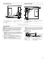
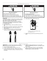
Upflow Installation
NOTE: Black hose is factory-connected to the 0.10" W.C.
pressure switch. Other end of hose must be field-connected to
flue pan. Remove plastic cap plug from
¹⁄₄
" port on flue pan
(discard cap plug) and connect hose to port.
IMPORTANT: Be sure that the pressure switch hoses do not
form a trap to hold condensation that could result from the flue
gas. Hose may be cut shorter to avoid forming a trap, if required.
Install Ductwork
IMPORTANT:
■
Install ductwork in accordance with NFPA 90B and any local
codes.
■
If there is no complete return air duct system, the return air
connection must be sealed to the furnace casing and run full
size to a location outside the utility room or space housing
the furnace to avoid a negative pressure on the venting
system.
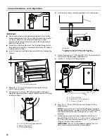
Installation with Return Ducts
A return air duct system is recommended. If the furnace is
installed in a confined space or closet, a return connection must
be run, full size, to a location outside the closet. The air duct in
the closet must be tight to avoid any entrance of air from the
closet into the circulating air.
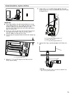
Installation with an Evaporator Coil
When an air conditioning furnace is used in conjunction with the
furnace, the evaporator coil must be installed in the discharge
(supply) air. Do not install an evaporator coil in the return air;
excessive condensation will occur within the furnace.
Installation without an Evaporator Coil
If a cooling coil is not installed with the furnace, then a removable
access panel should be provided in the supply plenum for
purposes of inspecting the heat exchanger. This opening must be
accessible when the furnace is installed. It must be large enough
that the heat exchanger can be viewed for possible openings
using light assistance or so that a probe can be inserted for
sampling the airstream. The cover for the opening must be
leakproof.
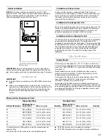
Filter Specifications
Upflow Models
A filter rack and cleanable 16" x 25" x
¹⁄₂
" (40.6 cm x 63.5 cm x
1.3 cm) filter are supplied with this furnace. (Models designed for
more than 1,600 CFM [487.7 m
3
/min] nominal air delivery include
two of each.)
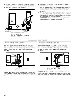
Some model furnaces can be installed with either a side or
bottom air return. For bottom air return the bottom air return
knockout plate must be removed.
For furnaces that do not include a side or bottom return filter
rack, Kit Number AFILT524-1 (side return) or Kit Number
AFILT529-1 (bottom return) can be used.
To provide sufficient filter area for installations requiring more
than 1,600 CFM (487.7 m
3
/min) nominal air delivery, return air will
have to be brought through both sides of the furnace, or through
one side and the bottom, or through a separate return air grille
not located on the product.
If a central return air filter-grille is used, the furnace does not
require a filter.
To install a filter at the furnace only, use the following kits:
■
AFILT524 for side return on upflow installations.
■
AFILT529 for bottom return on upflow furnace installations.
A. 0.10" W.C. pressure switch
B. Black hose
A
B
Minimum Filter Requirements Chart
Disposable Filters
Cleanable Filters
Airflow Descriptor
Minimum Area—
sq. in. (cm
2
)
Size—in. (cm)
Quantity
Minimum Area—
sq. in. (cm
2
)
Size—in. (cm)
Quantity
09
480 (3,096.8)
20 x 25 (50.8 x 63.5)
1
240 (1,548.4)
16 x 20 (40.6 x 50.8)
1
10
480 (3,096.8)
20 x 25 (50.8 x 63.5)
1
240 (1,548.4)
16 x 20 (40.6 x 50.8)
1
12
576 (3,716.1)
16 x 20 (40.6 x 50.8)
2
288 (1,858.1)
16 x 20 (40.6 x 50.8)
1
14
672 (4,335.5)
20 x 20 (50.8 x 50.8)
2
336 (2,167.7)
20 x 20 (50.8 x 50.8)
1
16
768 (4,954.8)
20 x 20 (50.8 x 50.8)
2
384 (2,477.4)
20 x 20 (50.8 x 50.8)
1
20
960 (6,193.5)
20 x 25 (50.8 x 63.5)
2
480 (3,096.8)
20 x 25 (50.8 x 63.5)
1
Содержание WFCT
Страница 31: ...31 Notes ...