


16
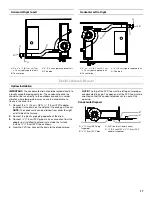
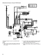
Nondirect Vent—Horizontal (Vertical Venting—Horizontal
Right to Left)
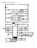
Nondirect Vent—Horizontal (Vertical Venting—Horizontal
Left to Right)
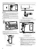
Connect Venting
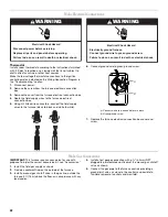
1. Run venting to the furnace, see “Plan Vent System.”
2. Attach the air intake pipe to the furnace connector.
Use high temperature RTV silicone sealant to attach the air
intake pipe into the connector on the burner box so the air
intake pipe can be removed if service is required.
NOTE: Do not use cement.
3. For nondirect vent installations only, install the inlet air
restrictor plate in the air inlet pipe. See Nondirect vents in
“Venting Requirements” for details.
4. Install tee assembly for condensate drain as shown
(horizontal applications only).
5. Attach the flue pipe connector to the furnace.
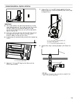
6. For both direct and nondirect vent installations, install the flue
pipe screen at the outside end of the flue pipe.
7. Make sure all vent connections do not leak.
8. Check that the exhaust vent pipe terminates outside the
building.
9. After the condensate disposal system has been installed,
prime the trap system by slowly pouring 8 oz (250 mL) of
water down the vent pipe. The vent pipe on horizontal runs
must slope upward, away from the furnace, at a minimum
pitch of
¹⁄₄
" (6.4 mm) per foot of run, to avoid accumulation of
condensate.
NOTE: On initial start-up of the furnace, some of the water
used to prime the trap system may run down into the
combustion blower and cause noise.
A. 6" (15.2 cm) minimum to roof. Adjust height
to expected snow level based on local
conditions.
B. Inlet air restrictor plate (inside inlet coupler)
C. Drain tee (in kit)
D. 3" (7.6 cm) long
piece of 2" (5.1 cm)
diameter pipe
A
B
C
D
A. 6" (15.2 cm) minimum to roof. Adjust height
to expected snow level based on local
conditions.
B. 3" (7.6 cm) long piece of 2" (5.1 cm)
diameter pipe
C. Drain tee (in kit)
D. Inlet air restrictor plate
(inside inlet coupler)
A
B
C
D
Содержание WFCT
Страница 31: ...31 Notes ...