background image

6

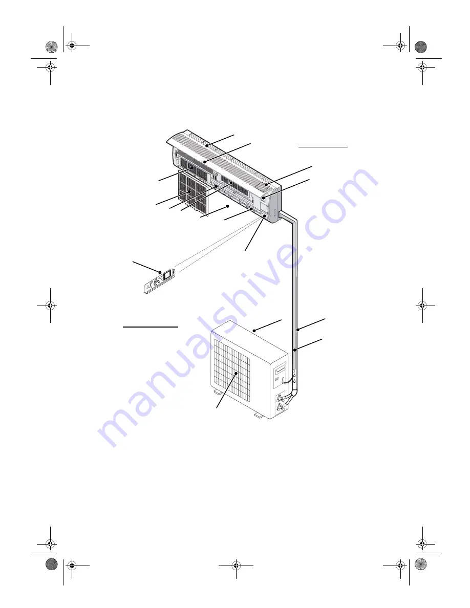
IDENTIFICATION OF PARTS

Indoor unit
A

- Air Intake

B

- Front Panel

C

- Operation Panel

D

- Display

E

- Air Outlet

F

- Vertical Adjustment Louver

G

- Horizontal Adjustment Louver

H

- Charcoal Filter (optional)

I

- Electrostatic Filter (optional)

L

- Remote Control

- Air Filter

Outdoor unit
N

- Air Intake

O

- Pipes and Power Connection Cord

P

- Drain Hose

Note: Condensate water drains 
at COOLING or DRY operation.

Q

- Air Outlet

R

- Rating plate (product tecnical data)

NOTE:
The figure above is only a simple presentation of the unit, it may not match the external appearance of the 
unit you purchased.

A

B

C

H

D

F

G

I

L

N

O

P

Q

Indoor unit

Outdoor unit

M

E

R

33933049GB.fm  Page 6  Monday, January 10, 2005  5:27 PM

Содержание SLIM RANGE R22

Страница 1: ...UCTIONS MAINTENANCE TROUBLESHOOTING PROTECTION INSTALLATION INSTRUCTIONS SLIM RANGE R22 SLIM RANGE This appliance is marked according to the European directive 2002 96 EC on Waste Electrical and Electronic Equipment WEEE This guideline is the frame of a European wide validity of return and recycling on Waste Electrical and Electronic Equipment 33933049GB fm Page 4 Monday January 10 2005 5 27 PM ...

Страница 2: ...unit for at least 5 seconds A buzz sound will signal that the auto restart function is cancelled and the air conditioner is in standby Be sure not to do the following It is harmful to your health if the cool air reaches you for a long time It is advisable to let the air flow be deflected to all the room Prevent the air flow from reaching the gas burners and stove Do not touch the operation buttons...

Страница 3: ...ntrol M Air Filter Outdoor unit N Air Intake O Pipes and Power Connection Cord P Drain Hose Note Condensate water drains at COOLING or DRY operation Q Air Outlet R Rating plate product tecnical data NOTE The figure above is only a simple presentation of the unit it may not match the external appearance of the unit you purchased A B C H D F G I L N O P Q Indoor unit Outdoor unit M E R 33933049GB fm...

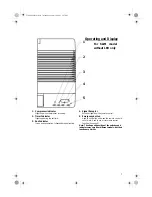
Страница 4: ...ives signal from the remote control 5 Emergency button Used to control the unit when the remote control is out of work Used to set or cancel auto restart function See page 5 Note The shape and position of the switches and indicators may vary from different models but their function are similar 1 2 3 5 4 Operating and Display For SLIM model without LED only 33933049GB fm Page 7 Monday January 10 20...

Страница 5: ...s up when unit is in sleep mode 4 Timer Indicator Orange It lights up during the set time 5 LED display Display set temperature when temperature is being set Display room temperature in other time 6 Run Indicator Green It is on during operation SILM model without LED SLIM model with LED Operating and Display 33933049GB fm Page 8 Monday January 10 2005 5 27 PM ...

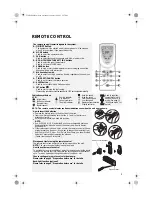
Страница 6: ... timer Used to regulate temperature in 6th Sense mode or Dry mode See page 11 6th Sense mode for details How to insert the batteries Remove the battery cover in the direction of the arrow Insert new batteries making sure that the and of battery are matched correctly Refit the cover by sliding it back into position NOTE Use 2 LR03 AAA 1 5 V batteries Do not use rechargeable batteries Replace batter...

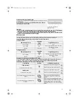
Страница 7: ...in the following pages IMPORTANT Changing modes during operation sometimes the unit does not response at once Wait 3 minutes During heating operation air flow is not discharged at the beginning After 2 5 minutes the air flow will be discharged until temperature of indoor heat exchanger rises Wait 3 minutes before restarting the appliance Airflow direction control 5 Airflow direction control Vertic...

Страница 8: ...1 5 C after operating for 3 minutes Over 26 COOLING 26 C Cooling only models Indoor temperature Operation mode Target temperature 26 C or below DRY Room temperature decreases 1 5 C after operating for 3 minutes Over 26 COOLING 26 C Important 6th Sense button is ineffective in JET mode Note Temperature airflow and direction are controlled automatically in 6th Sense mode However a decrease or rise o...

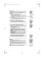
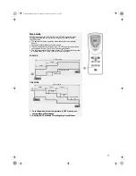
Страница 9: ...h flashes Choose the time you desire then press the TIMER button A beep can be heard Timer indicator on the indoor unit lights up h stops flashing Important Press the TIMER button h flashes on the LCD then you can set the time Each time the or button is pressed If the desired time is within 10 hours the set time increases or decreases by 0 5 hour If the desired time is beyond 10 hours the set time...

Страница 10: ... for two hours then it will remain constant The set temperature will decrease by max 3 C is the appliance operates in heating mode for 3 hours then it will remain constant COOLING HEATING In cooling mode if room temperature is 26 C or above set temperature will not change Heating is NOT available for cooling only air conditioner 1 hour 8 hours timer 1 hour Rise by 0 5 C SET TEMP START Rise by 0 5 ...

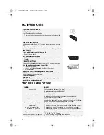
Страница 11: ...sty environment Trouble Analysis Does not run Is the protection device or fuse blown Sometimes it stops working to protect the appliance Are the remote control batteries low Is the plug unplugged No cool or warm air Is the air filter dirty Are the intakes and outlets of the air conditioner obstructed Is the temperature set properly Ineffective control Ifthereisastronginterference fromexcessivestat...

Страница 12: ... on the appliance immediately there may be a delay of 20 seconds before it starts to operate If all operation has stopped press ON OFF button again to restart Timer should be set again if it has been cancelled Install the air conditioner in a place that can bear its weight in order to operate more quietly Install the outdoor unit in a place where the air discharged and the operating noise do not a...

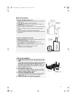
Страница 13: ...thorised personnel only Air outlet distance from the wall should be over 500 mm Distance from wall should be over 50 mm Distance from ceiling should be over 50 mm Distance from the wall should be over 50 mm Distance from floor should be over 2500 mm Air intake distance from the wall should be over 250 mm Air intake distance from the wall should be over 250 mm Over 250 mm Installation diagram 33933...

Страница 14: ...re operating noise will not increase Where the air outlet is not obstructed Outdoor unit installation 1 Install Drain Port and Drain Hose for heat pump model only The condensate drains from the outdoor unit when the unit operates in heating mode In order not to disturb your neighbours and protect the environment install a drain port and a drain hose to direct the condensate water Just install the ...

Страница 15: ... Fit the piping liquid and gas pipe and cables through the wall hole from outside or fit them from inside after completing indoor piping and cables connections so as to connect to outdoor unit Decide whether to saw off the plastic part in accordance with the piping direction as shown below NOTE When fixing the pipe along directions 1 2 or 4 saw the corresponding plastic part off the indoor unit ba...

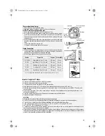
Страница 16: ...r Small pipe Thermallyinsulated tube Base Piping fixer Insert here Large pipe Drain hose Small pipe Hook here Unscrew and remove caps from 2 and 3 way valves Unscrew and remove cap from service valve Connect vacuum pump flexible hose to the service valve Start the vacuum pump for 10 15 minutes until it reaches an absolute vacuum of 10 mm Hg With the vacuum pump still running close the low pressure...

Страница 17: ...cable specification table below 3 Check the wires and make sure that they are all tightly fastened after cable connection 4 Be sure to install an earth leakage circuit breaker in a wet or moist area Cable Specifications Attention Accessibility to the plug must be guaranteed even after the installation of the appliance to disconnect it in case of need If not possible connect appliance to a double p...

Страница 18: ...d Terminal Terminal Brown Brown Blue Blue Power connecting cord Yellow Green Yellow Green HEAT PUMP COOLING ONLY Indoor unit Indoor unit Outdoor unit Outdoor unit Yellow Green Yellow Green Brown Brown Blue Blue Orange Orange Power connecting cord Terminal Terminal Terminal Power supply Orange Violet Violet Orange Black Black Brown Brown Blue Blue Y e l l o w G r e e n Y e l l o w G r e e n Power c...

Страница 19: ... protect the environment be sure not to discharge the refrigerant to the air directly Vacuum pump Connect to indoor unit Open position Spindle Needle Service port cap Valve core Connect to outdoor unit Indoor unit Refrigerant flow direction 3 way valve Service port 2 Turn 8 Tighten 7 Turn to fully open the valve 1 Turn 8 Tighten Valve cap 2 way valve 6 Open 1 4 turn 7 Turn to fully open the valve ...

Отзывы: