background image

STORAGE AND TIPS FOR USING THE
REMOTE CONTROL

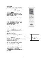
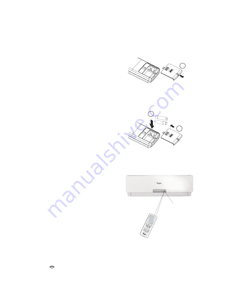
How to insert the batteries

1. Unscrew the screw on the battery cover.

Gently press down on the battery cover and
push in the direction of the arrow to remove, as
shown.

2. Insert 2 AAA batteries (1.5V) into the

compartment.
Ensure that "+" and "-" polarity is correctly
positioned.

3. Close the battery cover on the remote control.

Put back the screw on the remote control and
fasten it tightly.

How to remove the batteries

Unscrew the screw and remove the battery cover
in the direction of the arrow.
Press the positive pole of the battery softly with
your fingers, then draw the batteries out of the
compartment. 

children are forbidden to remove the batteries
from the remote control in order to avoid danger
of swallow.

Disposal of the batteries

Please discard the batteries as sorted municipal
waste at the accessible collection point.

Precautions

• When replacing the batteries, do not use new

batteries with old batteries, or different types of
batteries as this may cause the remote control
to malfunction.

•  If you do not expect to use the remote control

for some time, take the batteries out to prevent
leakage of battery acid in the remote control.

•  Operate the remote control within effective

range. Keep the remote control at least 1 meter
from any TV set or HI-FI equipment.

•  If the remote control does not work normally,

take the batteries out and reinstall after 30
seconds. If it still does not work install new
batteries.

•  To operate the appliance by remote control,

point the remote control at the receiving device
on the indoor unit, to ensure receiving
sensibility.

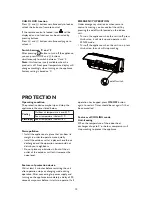
•  To send a message from remote control, the

symbol 

will flash for 1 second. On receipt

of the message, the appliance will emit a beep.

•  The remote control will operate the air

conditioner at a distance of up to 7m.

•  Each time the batteries are replaced in the

remote control, the remote control is pre-set at
6th Sense mode.

Appearance  may vary 

depending on the model you select

1

2

3

7

Caution:

 All this should be done by adults,

Signal receptor

Содержание SC009

Страница 1: ...SPLIT TYPE WALL MOUNTED ON OFF AIR CONDITIONER USER MANUAL AND INSTALLATION MANUAL MODELS SC009 SC012 SC018 SC022 ...

Страница 2: ......
Страница 3: ... they have had specific training on how to operate the appliance by a person responsible for their security and well being The appliance is not intended for use by disabled people and very young children without supervision Children should be supervised to ensure that they do not play with the appliance including remote control 1 AIR CONDITIONER PRECAUTIONS Please strictly follow the below instruc...

Страница 4: ...ing can be 100 recycled as confirmed by the recycling symbol The various parts of the packaging must not be dispersed in the environment but must be scrapped in line with local authority regulations SCRAPPING OF APPLIANCE By ensuring that this product is disposed of correctly you will help to prevent potentially negative consequences for the environment and for human health The symbol on the produ...

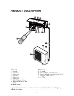
Страница 5: ...t Louver 8 Horizontal Adjustment Louver 9 Air Filter 10 Remote Control Outdoor unit 11 Air Intake 12 Pipes and Power Connection Cord 13 14 Air Outlet Images in the user instructions are based on external views of standard models shape and design vary according to the model 3 Drain Hose Note Condensate water drains at Cooling or DRY operation ...

Страница 6: ...s up in red when connecting to power supply It lights up in white or green during operation Heating indicator 3 It lights up during heating mode For heating model only Cooling indicator 4 It lights up during cooling mode Dehumidifying indicator 5 It lights up during Dehumidifying mode 9K 12K 18K 22K Signal Receptor 6 4 3 1 2 5 4 6 ...

Страница 7: ...p or start horizontal adjustment louver swinging and sets the desired up down airflow direction 9 POWER SAVE BUTTON Used to set or cancel power save operation 10 11 TIMER ON and TIMER OFF BUTTON Used to set or cancel the timer operation 12 DISPLAY ON OFF BUTTON Used to turn on off display light on indoor unit 13 INFO C BUTTON Used to display room temperature or set temperature on indoor unit contr...

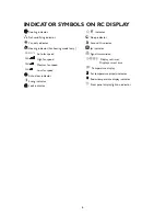
Страница 8: ... fan speed Medium fan speed Low fan speed Auto clean indicator Swing indicator Lock indicator indicator Sleep indicator Around U indicator Jet indicator Signal transmission Display set timer Display current time Temperature display Set temperature dispaly indicator Room temperature display indicator Front panel display light on indicator FAN F FAN FAN FAN ...

Страница 9: ...use new batteries with old batteries or different types of batteries as this may cause the remote control to malfunction If you do not expect to use the remote control for some time take the batteries out to prevent leakage of battery acid in the remote control Operate the remote control within effective range Keep the remote control at least 1 meter from any TV set or HI FI equipment If the remot...

Страница 10: ...G mode DEHUMIDIFYING mode FAN only mode HEATING mode For heating model only 3 Setting FAN speed Each time the Fan button is pressed the fan speed is changed in sequence Auto fan speed Low fan speed Medium fan speed High fan speed Only low fan speed is available under Dehumidifying mode 4 Setting temperature Press once to raise temperature setting by 1 C Press once to raise temperature setting by 1...

Страница 11: ... change of swing status will follow the sequence stated above Press SWING button continuously for more than 2s the main unit will swing back and forth from up to down and then loosen the button the unit will stop swinging and present position of louver will be kept immediately Vertical airflow control with hands Turn the control rods of the vertical adjustment louvers to change vertical air flow a...

Страница 12: ...e around it to the indoor unit and the appliance will operate according to this temperature to let you feel more comfortable Please keep the remote control in a location where it can transmit the signal to the indoor unit properly Press once to set and press again to cancel Indoor temperature Operation mode 22 C 26 C FAN or keep previous mode 26 C or over COOLING Your feeling button adjustment pro...

Страница 13: ... CLOCK button again the clock is set Pressing CLOCK button signal blink Within 5 seconds the value can be adjusted Press once to raise time setting by 1 minute Press once to lower time setting by 1 minute if continuously press or buttons the number will change rapidly 12 00 is the defaulted time to display after insert batteries SLEEP mode This function gives you a more comfortable environment for...

Страница 14: ...he set temperature will be displayed on control panel Pressing this button twice the icon on remote control will be changed to and the indoor room temperature will be displayed on control panel It will go back to set temperature after 5 seconds or once receiving other operation signal Note only set temperature is displayed on remote control POWER SAVE mode POWER SAVE mode can only be available in ...

Страница 15: ... t set the time in 5 seconds after you press TIMER ON button the remote control will exit the TIMER ON mode automatically II When your desired time is displayed on remote control press the TIMER ON button to confirm it A beep can be heard and ON indicator stops flashing How to cancel TIMER ON Press the TIMER ON button again a beep can be heard and the ON indicator disappears this function has been...

Страница 16: ...rking on off switch PROTECTION Operating condition The protective device maybe trip and stop the appliance in the cases listed below Noise pollution Install the appliance at a place that can bear its weight in order to operate more quietly Install the outdoor unit at a place where the air discharged and the operation noise would not disturb your neighbours Do not place any obstacles in front of th...

Страница 17: ... necessary to clean the air filter after using it for about 100 hours Clean the air filter every two weeks if the air conditioner operates in an extremely dusty environment 1 Disconnect from the power supply Turn off the appliance first before disconnecting from power supply 2 Take out air filter Fig B 1 Open the front panel 2 Press the handle of the filter gently 3 Slide out the filter 3 Cleaning...

Страница 18: ...n Peculiar smell This smell may come from another source such as furniture cigarette etc which is sucked in the unit and blown out with the air Check the air filter if they are very dirty and clean it A sound of running water Normal behaviour caused by the flow of refrigerant in the air conditioner Defrosting sound in heating mode for heating model Cracking sound The sound may be generated by the ...

Страница 19: ...al leakage protection switch and an air switch with sufficient capacity Refer to the following chart The air switch must also have a magnetic and a thermal tripping function to ensure protection in case of short circuit and overload 4 Make sure that the power supply cord is long enough to allow the right connection Do not use any extension cord for power supply 5 If the supply cord is damaged it m...

Страница 20: ...e national wiring standards by authorized service people only Distance from wall should be over 150mm Distance from ceiling should be over 150mm Distance from floor should be over 2500mm Distance from the wall should be over 150mm Air intake distance from the wall should be over 300mm Air intake distance from the wall should be over 300mm Air outlet distance from the wall should be over 2000mm Ove...

Страница 21: ... to the installation diagram The distance between Indoor and outdoor unit should be 5 meters and can go up to maximum 15 meters with additional refrigerant charge Do not install the outdoor unit in a dirty or greasy place near a vulcanization gas exit Avoid installing it at the roadside where it could be soiled with muddy water A fixed base where operating noise will not increase Where the air out...

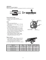
Страница 22: ... Piping Installation Fit the piping liquid and gas pipe and cables through the wall hole from outside or fit them from inside after completing indoor piping and cables connections so as to connect to outdoor unit Decide whether saw off the plastic part in accordance with the piping direction as shown below NOTE When fixing the pipe along directions 1 2 or 4 saw the corresponding plastic part off t...

Страница 23: ...d be thermally insulated and fixed at the rear of the unit Piping Connection a Connect indoor unit pipes with two wrenches Pay special attention to the torque allowed as shown below to prevent the pipes connectors and flare nuts from being deformed and damaged b At first fingers tighten them then use the wrenches Thermal insulation Wrapped with vinyl type 21 Pipe size Torque Nut width Min thicknes...

Страница 24: ...model It is necessary to remove the cabinet to perform connections with the indoor unit terminal Outdoor Unit 1 Remove the access door from the unit by loosening the screw Connect the wires to the terminals on the control board individually in accordance with the indoor unit connection 2 Secure the power connecting cord s installation properly with cable clamp 3 Refit the access door in the origin...

Страница 25: ...Drain Hose The condensate drains from the outdoor unit when the unit operates in heating mode In order not to disturb your neighbours and protect the environment install a drain port and a drain hose to direct the condensate water Just install the drain port on the chassis of the outdoor unit then connect a drain hose to the port as shown in the figure on the right 2 Install and Fix Outdoor Unit F...

Страница 26: ...elow Note Because the system pressure is high and also to protect the environment be sure not to discharge the refrigerant to the air directly Appearance may vary depending on the model you select How to Purge Air Tubes 1 Unscrew and remove caps from 2 and 3 way valves 2 Unscrew and remove cap from service valve 3 Connect vacuum pump flexible hose to the service valve 4 Start vacuum pump for 10 15...

Страница 27: ... found below the word Service on service sticker which is located on the side or on the bottom of the indoor unit The service number can also be found in the warranty booklet your full address your telephone number If repair work has to be carried out contact the Customer Care Centre Use of original spare parts and a proper repair is guarenteed You will need to present the original invoice Failure...

Отзывы: