- iii -
TABLE OF CONTENTS
GENERAL
............................................................................................................................... 1-1
Important Safety Information ................................................................................................ 1-1
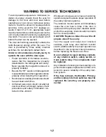
Warning To Service Technicians ......................................................................................... 1-2
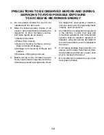
Precautions To Be Observed Before And During Servicing To Avoid
Possible Exposure To Excessive Microwave Energy ....................................................... 1-3
R.F. Leakage Test ................................................................................................................ 1-4
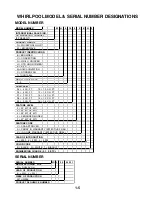
Whirlpool Model & Serial Number Designations .................................................................. 1-5
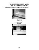
Model & Serial Number Label And Tech Sheet Locations ................................................... 1-6
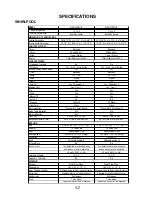
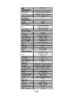
Specifications ....................................................................................................................... 1-7
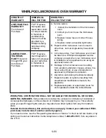
Whirlpool Microwave Oven Warranty ................................................................................. 1-11
THEORY OF OPERATION
..................................................................................................... 2-1
The Vent Motor Mounting Positions ..................................................................................... 2-1
The Oven Thermostat & Vent Motor Capacitor .................................................................... 2-2
The Vent & Turntable Motors ............................................................................................... 2-3
COMPONENT ACCESS
......................................................................................................... 3-1
Component Locations .......................................................................................................... 3-1
Removing The Turntable Motor & Cooktop Lamp Assembly ............................................... 3-2
Removing The Control Panel & Control Board .................................................................... 3-4
Removing The Door Switches .............................................................................................. 3-6
Removing The Oven Lamp Assembly .................................................................................. 3-7
Removing The Oven Thermostat, Line Fuse, & Power Cord ............................................... 3-8
Removing The Vent Motor Capacitor, The High
Voltage Capacitor, & Rectifier ......................................................................................... 3-10
Removing The High Voltage Transformer .......................................................................... 3-11
Removing The Magnetron .................................................................................................. 3-12
Removing The Vent Motor ................................................................................................. 3-13
Removing The Oven Door, The Switch Actuators,
And The Outer Glass ...................................................................................................... 3-14
COMPONENT TESTING
........................................................................................................ 4-1
Touch Panel Continuity ........................................................................................................ 4-1
The Turntable & Vent Motors ............................................................................................... 4-2
The Vent Motor Capacitor, Line Fuse, Oven Thermostat,
& Door Switch ................................................................................................................... 4-3
The High Voltage Capacitor & Rectifier ............................................................................... 4-4
The High Voltage Transformer ............................................................................................. 4-5
The Magnetron ..................................................................................................................... 4-6
WIRING DIAGRAM & STRIP CIRCUITS
............................................................................... 5-1
Wiring Diagram .................................................................................................................... 5-1
Strip Circuits ......................................................................................................................... 5-2
Page
Содержание MH6140XKQ/B
Страница 4: ... iv NOTES ...
Страница 16: ...1 12 NOTES ...
Страница 20: ...2 4 NOTES ...
Страница 46: ...5 4 NOTES ...
Страница 48: ...CORPORATION ...

