background image

WHIRLPOOL ELECTRICAL APPLIANCES CO. LTD.                                               SERVICE MANUAL 
 

Ref: 54158291a 


PAGE 10  OF 17 


7. 

MAJOR COMPONENT TESTS 


7.1 

HV TRANSFORMER 


1.


Remove lead wire. 

2.


Measure the resistance of the winding using an ohm meter 

3.


Primary winding  3 ohm (approx.) 

4.


Secondary winding   100 ohm (approx.) 

5.


Filament winding  0 ohm (approx.) 


7.2 

HV CAPACITOR 


1.


Remove lead wire 

2.


Measure the resistance using an ohm meter set to R*1000 

3.


Terminal  to  terminal  should  momentary  indicates  several  ohms  but  gradually 
increases to infinite. 

4.


Terminal to case should show infinite. 


7.3 

HV DIODE 


1.


Remove lead wire. 

2.


Measure forward resistance, normal diode show continuity. 

3.


Measure reverse resistance, normal diode show infinite resistance. 


7.4 

MAGNETRON 


1.


Remove lead wire. 

2.


Install the magnetron gasket in the correct position. Check that the gasket is in 
good condition. 

3.


Measure the resistance of the filament terminals. Normal magnetron should be 
less than 1 ohm. 

4.


Measure  the  resistance  between  the  filament  terminal  to  chassis.    Normal 
magnetron should be infinite. 


7.5 

INTERLOCK SWITCH SYSTEM 


IMPORTANCE:    The  installation  of  the  interlock  and  monitor  switches  are 
required by Federal regulations. 


Содержание 853854158291

Страница 1: ...POOL ELECTRICAL APPLIANCES CO LTD SERVICE MANUAL Ref 54158291a PAGE 1 OF 17 WHIRLPOOL ELECTRICAL APPLIANCES COMPANY LIMITED SERVICE INFO MANUAL MODEL AVM541 SKU No 853854158291 DATE October 6 2005 REVISION a ...

Страница 2: ...3 2 GROUNDING INSTRUCTIONS 4 SCHEMATIC DIAGRAM 5 MICROWAVE AND MICROWAVE LEAKAGE TEST 5 1 MICROWAVE TEST 5 2 MICROWAVE LEAKAGE TEST 6 TROUBLE SHOOTING GUIDE 6 1 CAUTION AND IMPORTANCE 6 2 MICROWAVE LEAKAGE 6 3 QUICK REFERENCE 7 MAJOR COMPONENT TESTS 7 1 HV TRANSFORMER 7 2 HV CAPACITOR 7 3 HV DIODE 7 4 MAGNETRON 7 5 INTERLOCK SWITCH SYSTEM 8 PART LIST EXPLODED DIAGRAM ...

Страница 3: ...ension H x W x D 285x456x392mm Volume of cavity 17 8Liter Basic function Microwave only cooking Control Mechanical timer control 60 minute timer 5 level microwave power level Power supply 220V 60 Hz single phase Output power Microwave 800W Power consumption Max 1250W Current consumption 8 A Microwave frequency 2450 MHz ...

Страница 4: ... closing 3 Seal and sealing surfaces arcing wear and other damage 4 Damage to or loosening of hinges and latches 5 Evidence of dropping or abuse c Before turning on the microwave power for any service test or inspection within the microwave generating compartments check the magnetron wave guide or transmission line and cavity for proper alignment integrity and connection d Any defective or misadju...

Страница 5: ...POWER BEFORE SERVICING RECONNECT ALL GROUNDING DEVICES All mechanical parts of this appliance capable of conducting electricity are grounded In the event of an electrical short circuit grounding reduces the risk of electric shock This appliance is equipped with a cord having a grounding wire with a ground plug The plug must be plugged into an outlet that is properly installed and grounded WARNING ...

Страница 6: ...WHIRLPOOL ELECTRICAL APPLIANCES CO LTD SERVICE MANUAL Ref 54158291a PAGE 6 OF 17 4 SCHEMATIC DIAGRAM ...

Страница 7: ...putting into the oven 3 Heat the water in the oven with full power microwave only for 60 seconds 4 Again measure the temperature of the water 5 If the temperature rise by about 10 degree Centigrade then the microwave generating system is working 5 2 MICROWAVE LEAKAGE TEST 5 2 1 TESTING EQUIPMENT 600cc beaker Microwave meter 5 2 2 TESTING PROCEDURE 1 Place 275cc of water into the beaker and place i...

Страница 8: ...OTING GUIDE 6 1 CAUTION AND IMPORTANCE 1 Before disassembling the oven the oven power must be turned off Remove the power plug of the oven from the outlet and wait for at least 3 minutes 2 When disassembling service personnel should remove their watches and metal chains from their hands Never touch the high voltage components and wire 3 Before checking or replacing discharge the high voltage capac...

Страница 9: ...adjusted interlock poorly adjusted causing fuse to be blown 5 Short circuit within electrical circuit Lamp filament short HV transformer short all causing fuse blown 6 Bad contact in contacts or terminals of timer switch primary and secondary interlock switch 7 HV diode break down Oven seems working food does not cook 1 Defective magnetron filament broken filament short to ground etc 2 Ground wire...

Страница 10: ...ncreases to infinite 4 Terminal to case should show infinite 7 3 HV DIODE 1 Remove lead wire 2 Measure forward resistance normal diode show continuity 3 Measure reverse resistance normal diode show infinite resistance 7 4 MAGNETRON 1 Remove lead wire 2 Install the magnetron gasket in the correct position Check that the gasket is in good condition 3 Measure the resistance of the filament terminals ...

Страница 11: ...itor switch will form a short circuit across the supply and the fuse in the oven will blow Electric arc may form across the switch contacts of the primary interlock switch and the monitor switch The switches may then be damaged If the fuse is blown due to the failure of the primary interlock repair the failed mechanical parts and replace all the interlock switches IMPORTANCE After replacement of a...

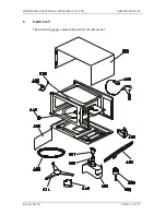
Страница 12: ...WHIRLPOOL ELECTRICAL APPLIANCES CO LTD SERVICE MANUAL Ref 54158291a PAGE 12 OF 17 8 PART LIST The following pages contain the part list for this model ...

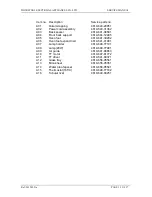
Страница 13: ...01 A04 Front back support 4619 644 12485 A05 Oven foot 4619 641 39202 A06 Oven foot expand nail 4619 641 41901 A07 Lamp holder 4619 648 77101 A08 Lamp 20W 4619 648 77091 A09 Air guide 4619 641 88863 A10 TT motor 4619 647 81772 A11 TT driver 4619 641 89371 A12 Glass tray 4619 656 95561 A13 Mica sheet 4619 656 95351 A14 Water proof spacer 4619 656 95541 A15 Thermostat 165 C 4619 648 77182 A16 Tubula...

Страница 14: ...B04 HV capacitor 4619 646 51103 B05 HV diode 4619 646 97721 B06 Fan air guide 4619 641 89323 B07 Fan motor 4619 647 81511 B08 Fan wheel five 4619 641 89262 B09 Interlock assy 4619 640 39241 B12 Fuse holder 4619 648 77391 B13 Fuse 4619 648 81241 B14 HV transformer 4619 648 77426 B15 Rubber 4619 640 31661 B16 Foam 4619 656 95811 B17 Double HV diode 4619 646 97821 B01 B02 B03 B04 B05 B06 B07 B08 B09 ...

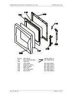
Страница 15: ...Item no Description Service parts no C01 Door body assembly 4619 640 47831 C02 Inner foil C03 Inner frame 4619 641 89341 C04 Extension spring 4619 644 11221 C05 Glass support 4619 641 89401 C06 Door hook 4619 641 91032 C07 Front door glass 4619 656 95371 C08 Door frame 4619 641 88852 ...

Страница 16: ...91a PAGE 16 OF 17 Item no Description Service parts no D01 Timer 4619 648 33161 D02 Control panel 4619 641 89611 D03 Knob D04 Spring Bushing 4619 640 45881 D05 Spring Coil Other information Item no Description Language Service parts no 01 IFU English 4619 652 60744 ...

Страница 17: ...IANCES CO LTD SERVICE MANUAL Ref 54158291a PAGE 17 OF 17 Revision Log Revision Description Revised by Revision Date 0 Original Revision Wang Wei Guo Sep 20 2001 a Revising PN in the service part list Liang min yi October 6 2005 ...

Отзывы: