background image

MICROWAVE HOOD COMBINATION

INSTALLATION INSTRUCTIONS

MICROWAVE HOOD COMBINATION SAFETY

This product is suitable for use above electric or gas cooking products up to 36" (91.4 cm) wide.
These installation instructions cover different models. The appearance of your particular model may differ slightly from the 
illustration in these installation instructions.

NOTES:

Proper installation is the responsibility of the installer.

Product failure due to improper installation is not covered under the warranty.

Table of Contents

MICROWAVE HOOD COMBINATION SAFETY .............................. 1

VENTING DESIGN SPECIFICATIONS.............................................. 2

INSTALLATION REQUIREMENTS ................................................... 3

Tools and Parts............................................................................... 3
Location Requirements................................................................... 4
Product Dimensions ....................................................................... 4
Electrical Requirements .................................................................. 5

INSTALLATION INSTRUCTIONS ..................................................... 5

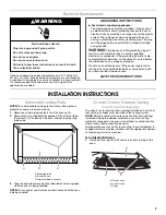
Remove Mounting Plate ................................................................. 5
Convert Oven to External Venting .................................................. 5
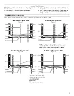
Locate Wall Stud(s) ......................................................................... 7
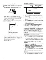
Mark Rear Wall................................................................................ 8
Drill Holes in Rear Wall.................................................................... 8
Attach Mounting Plate to Wall ........................................................ 9
Prepare Upper Cabinet................................................................. 10
Install the Oven ............................................................................. 10
Complete Installation .................................................................... 12

ASSISTANCE ................................................................................... 12

Replacement Parts ....................................................................... 12
Accessories................................................................................... 12

IMPORTANT: Read Installation Instructions thoroughly before beginning installation. Save Installation Instructions for local house 
inspector’s use.

8205272

You can be killed or seriously injured if you don't immediately 
 

You


can be killed or seriously injured if you don't follow 

All safety messages will tell you what the potential hazard is, tell you how to reduce the chance of injury, and tell you what can
happen if the instructions are not followed.

Your safety and the safety of others are very important.

We have provided many important safety messages in this manual and on your appliance. Always read and obey all safety 
messages.

This is the safety alert symbol.

This symbol alerts you to potential hazards that can kill or hurt you and others.

All safety messages will follow the safety alert symbol and either the word “DANGER” or “WARNING.”

These words mean:

follow instructions.

instructions.

DANGER

WARNING

Содержание 8205272

Страница 1: ...Attach Mounting Plate to Wall 9 Prepare Upper Cabinet 10 Install the Oven 10 Complete Installation 12 ASSISTANCE 12 Replacement Parts 12 Accessories 12 IMPORTANT Read Installation Instructions thoroughly before beginning installation Save Installation Instructions for local house inspector s use 8205272 You can be killed or seriously injured if you don t immediately You can be killed or seriously ...

Страница 2: ...he damper to open fully If venting through the roof and rectangular to round transition is used be sure there is at least 3 7 6 cm of clearance between the top of the microwave oven and the transition piece See Rectangular to Round Transition illustration Rectangular to Round Transition NOTE The minimum 3 7 6 cm clearance must exist between the top of the microwave oven and the rectangular to roun...

Страница 3: ...teners NOTE Depending on model aluminum grease filter and charcoal filter may be combined Materials needed Standard fittings for wall or roof venting See Venting Design Specifications section A One 3 x 10 8 3 x 25 4 cm 90 elbow 25 ft 7 6 m B 1 wall cap 40 ft 12 2 m C 2 ft 0 6 m 6 ft 1 8 m straight 8 ft 2 4 m A B C 6 ft 1 8 m 2 ft 0 6 m A Two 90 elbows 20 ft 6 1 m B 1 wall cap 40 ft 12 2 m C 1 rect...

Страница 4: ...Only The 12 x 4 30 5 x 10 2 cm cutout area see Wall Venting Installation Only in the Mark Rear Wall section must align with the wall damper vent on the back of the oven see Wall Venting Installation Only in the Convert Oven to External Venting section Cutout must be free of any obstructions so that the vent tube fits properly and the damper blade opens freely and fully For Roof Venting Installatio...

Страница 5: ...re the oven for wall or roof venting the vent deflector L shaped metal bar must be installed and the appropriate damper vent opening must be uncovered To Install Vent Deflector 1 Gently pull the rings and lift vent screen from the top of the oven Electrical Shock Hazard Plug into a grounded 3 prong outlet Do not remove ground prong Do not use an adapter Do not use an extension cord Failure to foll...

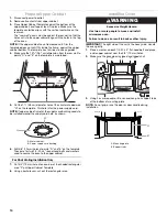
Страница 6: ... possible change of venting method in the future 4 Position the damper assembly so that the long tab slides into the slot on the right side of the damper vent opening as shown Then secure with mounting screw Roof Venting Installation Only To Remove Roof Damper Vent Cover 1 Locate the roof damper vent cover on the top of the oven 2 Using diagonal wire cutting pliers gently snip out the damper vent ...

Страница 7: ... Studs at Corner Holes Figure 1 No Wall Studs at Corner Holes Figure 2 NOTE If wall stud is within 6 15 2 cm of the vertical centerline see Mark Rear Wall section only ventless recirculating or roof venting installation can be done One Wall Stud at Two Corner Holes Figure 3 Wall Studs at All Four Corner Holes Figure 4 A Corner holes on mounting plate B Cabinet opening vertical centerline C Wall st...

Страница 8: ... x 4 30 5 x 10 2 cm rectangle This is the venting cutout area 11 Cut a 3 4 19 mm hole in one corner of the cutout area 12 Using a keyhole saw cut out the venting cutout area Drill Holes in Rear Wall In addition to being installed on at least 1 wall stud the mounting plate must attach to the wall at all 4 corner holes If the holes are not over wall studs use four 1 4 20 x 3 round head bolts with to...

Страница 9: ... 3 1 With the support tabs of the mounting plate facing forward insert 1 4 20 x 3 round head bolts through the 2 corner holes that fit over the two 3 4 19 mm holes drilled in Step 2 of Installation for One Wall Stud at Two Corner Holes in the Drill Holes in Rear Wall section 2 Start toggle nuts on the bolts from the back of the mounting plate Leave enough space for the toggle nut to go through the...

Страница 10: ... to be installed around the supply cord hole as shown 6 Drill 3 8 10 mm holes at points D and E on the template These are for two 1 4 20 x 3 round head bolts and washers used to secure the oven to the upper cabinet For Roof Venting Installation Only 7 Cut 3 4 19 mm hole at one corner of the shaded rectangular area F on Upper Cabinet Template 8 Using a keyhole saw cut out the rectangular area Insta...

Страница 11: ...binet into oven Tighten bolts until there is no gap between upper cabinet and oven NOTES Some upper cabinets may require bolts longer or shorter than 3 7 6 cm Longer or shorter bolts are available at most hardware stores Overtightening bolts may warp the top of the oven To avoid warping wood filler blocks may be added The blocks must be the same thickness as the space between the upper cabinet bot...

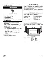
Страница 12: ...frame of the microwave oven If you need additional assistance call us at our toll free number listed in the Use and Care Guide or visit us on the Web Replacement Parts If any of the installation hardware needs to be replaced call us at our toll free number listed in the Use and Care Guide and reference the appropriate part number listed here Accessories Filler Panel Kits are available from your de...

Отзывы: