Page 4
I: INTRODUCTION
The PCC-S9N is designed to operate any EDGE 9000
®
or
ADVANTEDGE
®
lightbar if equipped with an internal relay/
matrix board. In addition to controlling lightbar functions,
the PCC-S9N has a siren turn-on feature. This feature
gives the operator true single lever control over both pri-
mary warning light and siren functions on slide switch
position 3 (See pages 3 and 4). The PCC-S9N is designed
to operate on a 12 volt D.C. vehicular electrical system.
II: MOUNTING
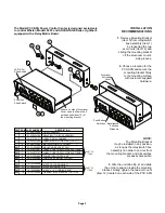
(Also, pg. 1) When choosing a mounting location for the
PCC-S9N consider the following: The PCC-S9N should be
located so that the driver can operate the controls without
taking his eyes off the road. Interconnecting cables should
be easily accessible to facilitate installation. The PCC-S9N
is supplied with a universal mounting bracket that may be
attached either above or below the switch housing. Deter-
mine which holes in the mounting bracket are to be used,
then loosely assemble the bracket and bracket hardware
(See page 1). Slide the head of the carriage bolt into the
slot in the side of the switch housing. Position the PCC-
S9N in the desired mounting location and trace the outline
of the mounting bracket. Remove the mounting bracket
from the switch housing. Align the mounting bracket with
the outline traced in the previous step, and trace the out-
line of the mounting slots. Positioning the mounting hard-
ware (customer supplied) in the center of each mounting
slot, for maximum side to side adjustment. Attach mount-
ing bracket, and when in position tighten the acorn nuts.
III: WIRING.
The PCC-S9N is supplied with two wire
harnesses exiting the rear of the switch housing. Before
attempting any wiring, make sure all switches are in the
“OFF” position. The slide switch must be in the full left
position and all push buttons must be in fully extended
position.
A.
The nine wire harness is designed to plug directly into
the end of an EDGE
®
or ADVANTEDGE
®
lightbar cable
equipped with a mating connector. If retro-fitting a lightbar
not supplied with a mating connector, crimp AMP pins
(Whelen part number 39-0501316-04) on the wire ends
and insert them into an AMP nine pin connector (Whelen
part number 39-0409313-04). Make sure the wire colors
match up when the connectors are mated.
B.
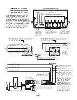
The four wire harness from the switch housing has a
mating harness supplied in kit form. The loose black/white
wire and the white/green wire should only be inserted into
the connector if their functions are used (see page 3).
1.
The black/white wire is the +12 VDC (positive) output
from push button switch #6 and is rated at 250 mA. An
external relay (not supplied) is recommended for the use
of this circuit. If you wish to use this feature, insert the
loose black/white wire into the connector in position #4.
For ON-OFF operation use Bosch relay 0 332 014 150
(Whelen part number 30-1712001-08) or equivalent. For
HORN/SIREN operation use Bosch relay 0 332 204 150
(Whelen part number 30-2612021-08) or equivalent. (Pg.
3 wiring)
2.
The supplied white/green wire assembly is an auxiliary
output from the slide switch position #3 (red led indicator).
Its purpose, when connected to a Whelen siren amplifier,
is to turn on both the siren and a primary warning light
function when the slide switch is operated in position #3.
The siren tone is determined by the setting of the siren
function control knob. Refer to your siren amplifier’s
installation manual to learn how to utilize this feature.
3.
Connect the black wire to a good electrical ground
(NEGATIVE).
4.
The red wire is the power feed for switches 2 through
7, as well as the red/green led indicators for these
switches. This wire should be connected to the vehicle
fuse block “ACCESSORY OUTLET”. This circuit is fused
on the relay board at 5 amps with fuse F1. (See page 5).
Failure to use the “ACCESSORY OUTLET” will cause the
led indicators to remain on, and drain the vehicle battery.
IV: OPERATION
With all electrical connections made, and the vehicle
accessory outlet “ON”, the PCC-S9N will display the fol-
lowing characteristics: Slide switch LED indicators will be
off, and green LED indicators will be lit behind the func-
tion windows located above the push button switches. As
the slide switch is moved progressively to the right, the
green, yellow and red LED indicators will turn on in
sequence, as well as the corresponding lightbar func-
tions. As each push button switch is depressed, the green
LED indicator will change to red and the corresponding
lightbar function will turn on.
NOTE:
Switch #7 is a momentary contact switch for
strobe low power, and will work only if the lightbar strobe
lights are operating. Switch #7 will display a red indicator
only while pressed in, however the strobe lights will oper-
ate in low power until the power to the strobe lights is
turned off. Turning the strobe lights off and then on, will
reset the high power function.
V: FUNCTION LABELS:
The PCC-S9N is supplied with an assortment of com-
monly used function labels. Verify the function of each
switch. Peel the labels from the backing sheet and stick
on the front of the appropriate switch function window.


