


page 1 - 3
EDGE Network / Jan 2016
G E N E R A L I N F O R M A T I O N
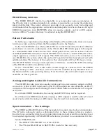
The EDGE alleviates this random latency problem by adding a buffering mechanism
between the radio and the network. The EDGE can be located at either end of the link,
but the way it operates with WheatNet‑IP depends which end it is located on. For both
cases, the internal hardware of EDGE remains mostly the same. Small .25 msec packets are
ingested,bufferedandrepackagedas5msecpackets.Thereare4instancesofthisRX-TX
mechanism which we have denoted as BIG for signal name defaults.
Variable Delay
Set By GUI
Variable
Delay
Set By GUI
Navigator
Matrix
EDGE Buffers
1-4
Large Packets
Sources
Analog
AES
1
2
3
4
1
2
3
4
1 2 3 4
5 6 7 8
5
6
7
8
Destinations
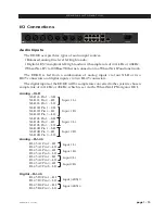
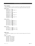
EDGE Audio Outputs
EDGE Audio Inputs
DAC
DAC
AES
AES
5ms
Fixed
1
3
2
4
EDGE Function
AUDIO DESTINATIONS
AUDIO SOURCES
BLADES
BLADES
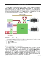
EDGE Installation Options
The EDGE may be installed at either the Studio or Transmitter sides of the IP‑STL link.
Where you decide to install it depends on a few factors:
•
IP Radio quality
•
BLADE infrastructure
•
Cost.
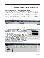
EDGE Installed on the Studio Side
For a “Studio‑Edge” IP‑STL application, the EDGE connects to the WheatNet‑IP Ethernet
network located at the studio end of link and a BLADE is then located at the transmitter
(TX)end.TheTXsideBLADEconnectstoanotherEthernetswitchalongwiththeIPRadio.
In this case, PGM audio from a control room needs to get through an IP radio to the
transmitter site. In Navigator, the desired PGM mix Source is routed to one of the four
EDGE Buffers. EDGE Buffer inputs automatically appear as Destinations in the Naviga‑
tormatrixwhentheEDGEisfirstconfigured.Likewise,theEDGE’spost-delay,Buffered
outputs automatically appear as Sources in the Navigator matrix.