background image

27

Depending on the type of the model aircraft used, 

choose among the following model types. There are 
three options for helicopter, Airplane and glider, and 
multi-rotor in the transmitter. The list in the model 
function will also change according to the selected 
model.

Notice:

The ET07 has three voltage detection alarms. In 

addition to the transmitter voltage, the receiver and 
the receiver's external battery, the two voltage 
values will only take effect if the "telemetry" function 
is turned on.

The setting of the low voltage should be set 

according to the battery capacity, type, old and new 
battery factors. In order to avoid the loss caused by 
the low voltage automatic shutdown, please drop 
the model in a safe situation as soon as possible 
after the alarm.

Enter the interface:

→ System Setting → 

WFLY

Low Voltage

Setting method:
Press the key - select the setting item after pull 

the arrow key ; press the plus or minus button to 
adjust the value, press and hold the confirm button 
to reset the value; press the return key to exit the 
interface and save the setting.

Touch screen - click on the number you want to 

set, the "Plus", "Reset", "Reset" buttons will pop up 
on the right side. Click the function name on the 
upper left corner to save the setting.

Low Voltage reference value:
1. Transmitter
Lithium battery: 3.7V

2. Receiver
1S Li-Po battery: 3.7V
2S Li-Po battery: 7.4V
ESC (5V) power supply: 4.7V (if high voltage 8.4V 

power supply,

Then set to 7.4V. )

3. External
When using lithium battery: S × 3.7V (S is the 

number of lithium batteries, such as 2S lithium 
battery, then S=2. );

For other battery types, please follow the 

instruction manual of the battery you are using to 
set.

R X

NO R M

4.2V

3

.

7V

4

.

2V

0

.

0V

Low Voltage

Transmitter

Receiver

External

0 0 : 0 6 : 5 9

Plus

Reset

Subtract

Low Voltage

Turns the operation on and off to trigger the 

sound.

Note: 

This function can only set the prompt sound 

of the interface operation (button, touch screen 
operation), does not affect the function prompt 
(timer), alarm and other sounds!

Enter the interface:

 → System Setting → 

WFLY

Sound

Setting method:
Press the key - press the plus or minus key or the 

confirm key to switch the switch state, press the 
return key to exit the interface and save.

Touch screen - click the switch key to switch the 

status, click the function name in the upper left 
corner to exit the interface and save.

R X

NO R M

4.2V

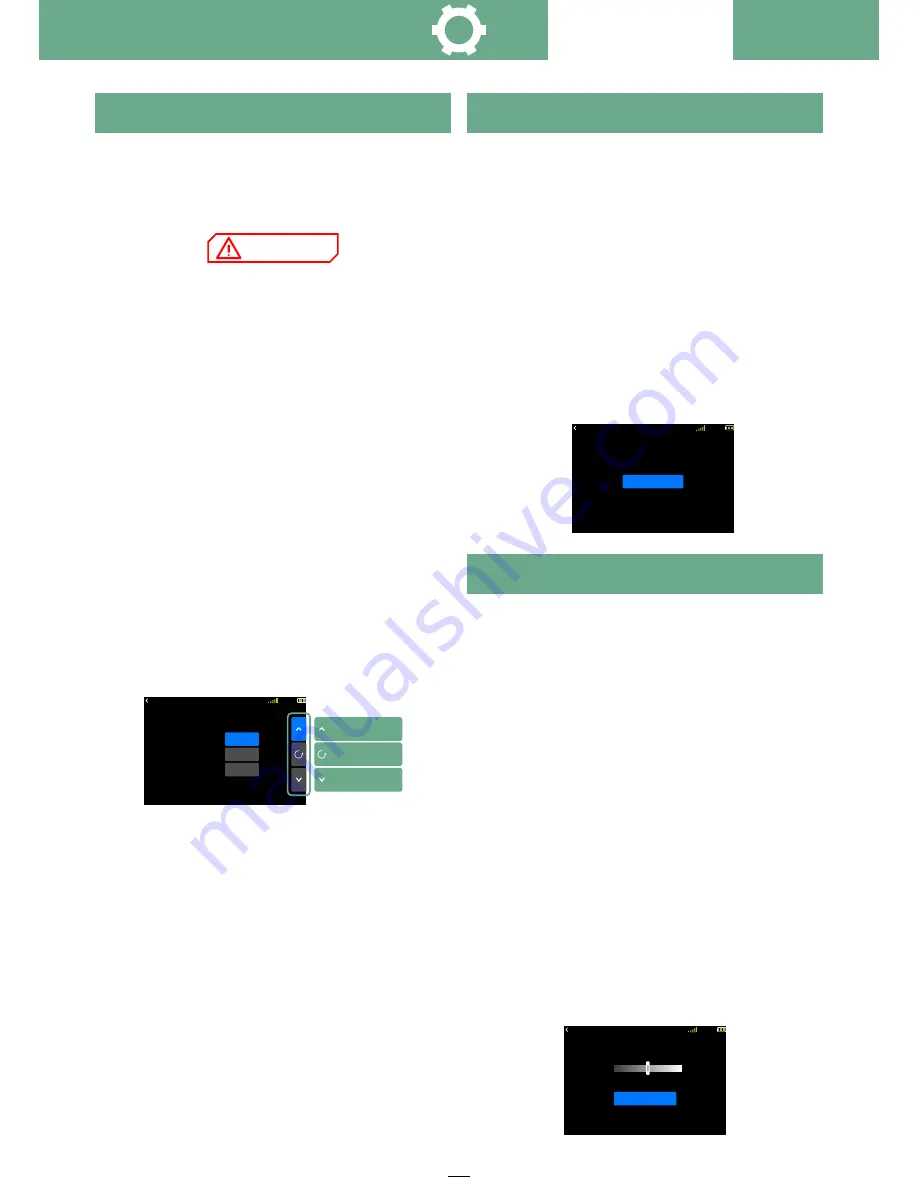
Sound

Sound

O N

0 0 : 0 6 : 5 9

Sound

Backlight

Adjust the brightness of the display backlight to 

suit different usage environments.

Note: The backlight time means that when the 

button and touch screen operation are not detected, 
the backlight will automatically decrease after the 
set value time! The backlight can be set to be bright 
according to the needs of use!

Enter the interface:

 → System Setting→ 

WFLY

Backlight

Setting method:
1 Brightness setting

Press the button to set the value, press and hold 

the OK button to reset to

50% brightness. Press the Back button to exit the 

interface and save.

Touch panel - click or drag the slider to change the 

brightness, click on the upper left corner

Can name the interface and save it.

2 Backlight time

Press the key - plus-subtract key to set the value, 

press and hole the OK key to reset the value.Press 
the Back button to exit the interface and save.

Touch screen - click to switch the time slot, click 

on the function name in the upper left corner,exit the 
interface and save

R X

NO R M

4 . 2V

Back Light

Back Light

Time

5 0

%

15Sec

0 0 : 0 6 : 5 9

System Setting

NOTICE

Содержание ET07

Страница 1: ...1 Shezhen WFLY Technology Development Co Ld 10 Channels Digital Proportional R C System ET07 More product information please follow the WeChat official account above Instruction Manual V1 04 ...

Страница 2: ...ank you for using WFLY products Please read this product manual carefully before using this product Please use this product properly The R C model is not a toy for safety please do not fly in crowded places ...

Страница 3: ...terface Before Use Product Features Basic Configuration Each Parts Name Of Transmitter Switch Configuration And Types The Travel Of Antenna Direction Adjustment Basic Operation Home Interface Operation Touch Screen Operation Indicator Light Of Transmitter Stick Adjust Instruction Stick Adjustment Receiver Instructions Receiver And Servo Link Example airplane glider helicopter multicopter Models Ba...

Страница 4: ...de Language Factory Reset Telemetry Unit Screen Cal Information 32 33 33 34 35 36 36 36 Linkage Setting Link Step Telemetry Servo Frequency Range Check Fail Safe W BUS Servo PPM W BUS Rx Port Setting Transmitter and receiver link Display the set sensor data The servo working frequency Reduce the power to remote control range check When the receiver lost the signal it automatically loads the preset...

Страница 5: ...p and aileron Combined aileron and elevator mixed control Adjust ELE and AIL one way mix Adjust elevator and rudder mixed control Model Menu Helicopter Throttle Hold Throttle Curve Swash Fly Mode Throttle Cut Pitch Curve Idle Down Governor Gyro Hold the throttle output status Adjust the liner relation of throttle Select swash types and set swash parameters Motion mode assignment To make instant th...

Страница 6: ...may cause dangerous accident or seriously injury or may even cause death and it may cause slight hurt or probability cause bodily injure If without a proper operation it may cause less possibility to serious hurt but it may cause hurt or bodily injure Pay special attention to the safety information of the following symbols WARNING DANGER NOTICE Prohibitions Compulsory Items ...

Страница 7: ...e aircraft are normal When flying make the interface of transmitter in the initial interface for preventing the change of parameters by mistake After flying turn off the receiver primarily and then turn off the transmitter for protecting people from the fail safe function More debugging more testing less loss less damage Power on and off sequency of transmitter and receiver Power on step Firstly t...

Страница 8: ...DO NOT allow the battery s internal electrolyte to get into eyes or on skin wash affected areas immediately if they come in contact with the electrolyte If in doubt place the battery in a fire proof location for at least 30 minutes 12 Do not store batteries near an open flame or heater DANGER Battery Safety Caution Transmitter trainer port The trainer port is with 3 5mm audio port output mode This...

Страница 9: ... GHz Working Voltage 3 7 V 8 4 V Working Current 75 mA Applications Helicopter Airplane Multi Rotors Vehicle Ship Resolution Full Channel 4096 Resolution PWM 7 Channel Mode A PPM Support W BUS Compatible with S BUS W BUS2 Telemetry Sensor Input Bidirectional Transmission Support Fail Save Support Online upgrade Support External voltage detection DC 0 96V Size 27 14 51mm Weight 14 6g Basic Configur...

Страница 10: ... key Trainer port Power LED RF Light SD SC V2 Slide Lever V1 Rotary Knob Trim T1 Navigate Key Power switch USB Interface Resistance touch screen Stick Hook Battery compartment Antenna Trim T4 Trim T3 Trim T2 Carry handle Battery Interface Before Use ...

Страница 11: ... click to return to standby interface click and hold for 2 seconds to turn on the monitor interface EXIT Return key slightly return to the superior interface Click and hold for 2 seconds screen lock and unlock Increase key parameter increment switch status Decrease key parameter decrement switch status Up down left right Direction key Middle Slightly click to confirm press and hold to reset parame...

Страница 12: ...ter current machine type Interface 10 User name click into user defined name 11 Trim status display T1 T4 trim status T1 T4 while the switch being used more details please refer to Aux Channel and Trim Setting means the position is up means the position is neutral means the position is down 12 Transmitter battery capacity 13 Receiver signal strength 14 Fly mode Throttle lock normal Idle1 Idle2 15 ...

Страница 13: ...oftly with the stylus pen or your fingertips Plastic film is attached to the touch screen Please be careful so that you don t scratch the touch screen with anything hard such as a metal object Don t push the touch screen with excessive force or drop anything on the panel Operate Demonstration Menu Operation Click enter into the relative interface Status Switch Click into switch status Parameters S...

Страница 14: ...ise the structure assembly would be twisted off and the screw may fall off resulting in irreversible damage Soft silicon uncover method Upper and lower feeling adjustment position Upper and lower elastic adjustment position Left and right elastic adjustment position Tooth adjustment Smooth adjustment Upper and lower feeling adjustment position Upper and lower elastic adjustment position Smooth adj...

Страница 15: ... stick can be changed by adjusting the height of screw 3 2 Remove the screw of the throttle reed the throttle reed and the throttle sleeve and install them in the corresponding position of the other assembly According to your own habits select the type of throttle sliding toothed and smooth and adjust the screw screw 1 or The height of the screw 2 makes the damping of the throttle conform to your ...

Страница 16: ...ctor placed on both sides of the fuselage and it is better to make the antenna leak outside the model casing In this way good signal reception can be maintained regardless of the flight attitude 2 When the antenna is installed The unshielded end of the antenna should be as far away as possible from the conductor materials such as metal and carbon fiber The antenna cable avoids bending at large ang...

Страница 17: ...fferential 1 FLP CH6 AIL1 CH1 AIL2 CH7 ACRO Ailvator 3 AIL1 ELE2 CH1 FLA2 ELE1 CH2 Servo connection position Airplane The table below shows examples of the servo connection positions for the different wing types and tail types Airplane ACRO 1 Aileron Aileron1 1 1Aileron1 Aileron2 2 Aileron1 Elevator2 3 2 Elevator Elevator1 Aileron2 3 Elevator1 Rudder2 4 3 Throttle 4 Rudder Rudder1 Elevator2 4 5 Sp...

Страница 18: ...1 FLP CH5 AIL 1 Servo CH1 Aileron Elevator Motor Rudder Flap Flap 2 Aileron2 Aileron Elevator Motor Rudder Flap Auxiliary Aileron2 Aileron Elevator Motor Rudder Auxiliary Auxiliary Aileron2 Aileron Elevator Motor Rudder Auxiliary Auxiliary Auxiliary 1AIL A 1 CH 2 3 4 5 6 7 1 Basic Operation Receiver and servo Link example Tail 2AIL A 2 2A 1F AF1 2A 2F AF2 1AIL A 1 2AIL A 2 ELE2 RUD1 CH4 ELE1 RUD2 ...

Страница 19: ...H2 ELEVATOR CH1 AILERON CH5 GYRO GRO Helicopter The figure below shows an example of helicopter link Please use the actual wing type and tail type for servo link CH6 PITCH Elevator Pitch Aileron HE3 Elevator Pitch Aileron HN3 120 HR3 120 Elevator Pitch Aileron Elevator Aileron Pitch H 3 Basic Operation 1 Aileron 2 Elevator 3 Throttle 4 Rudder 5 Gyro 6 Pitch 7 AUX Governor Receiver output channel H...

Страница 20: ...e below shows the four rotor multicopter Please refer to the model manual for specific applications Motor electronic speed controller flight controller battery etc are sold separately MULTI COPTER 1 Aileron 2 Elevator 3 Throttle 4 Rudder 5 Spare 6 Spare 7 Spare Receiver output channel CH1 AILERON CH2 ELEVATOR CH3 THROTTLE CH4 RUDDER CH5 Receiver and servo Link example Basic Operation Use 5CH 9CH w...

Страница 21: ...rom the root to a range of 14 to 15 mm If you need to adjust It can be adjusted in the range of 90 110 Elevator setting After adjustment the upper and lower movements are also about 15 mm Rudder setting After adjustment the left and right motion range is about 45 Models Basic Setting Sequence Dual Rate adjust The rate adjustment after flight is performed by the Dual Rate function Initially adjust ...

Страница 22: ... to prevent the throttle from suddenly starting to cause danger Normal Used when the engine starts to hover Idle1 Use when flying in the air etc Idle2 Use during air roll and other operations 3 Normal setting Firstly normal setting Turn off Idle to normal status Throttle curve Call up throttle curve menu select Advanced Throttle curve initial setting is according to the below figure value This set...

Страница 23: ...the table below This curve ensures that the throttle stick is placed in the low position and still maintains the amount of idling increase in rotation Pitch Curve Bring up the Pitch Curve menu and set the curve to Advanced The values are set according to the below table The setting of the high pitch is the same as the setting of the Idle 1 The curve is set as shown in the figure Now the pitch sett...

Страница 24: ... name change And Return ro the model name list OK Exit The model names stored in ET07 can be changed The currently selected model name will always be displayed on the standby screen This makes it easy for us to distinguish between different model settings and to prevent incorrect calls to other stored information The name of each model consists of up to 9 characters Enter the interface System Sett...

Страница 25: ...FLY Model Type RX NORM 4 2V Model Type 00 12 02 Multicopter Type Confirm 00 12 02 RX NORM 4 2V Model Type Airplane Glider Type Confirm RX NORM 4 2V Model Type 00 12 02 Helicopter Type Confirm RX NORM 4 2V Model Type Confirm Multicopter Type NO OK Model type is changed Confirm 00 06 59 Press the key select the Model Type key press the confirm key or the plus or minus key to switch the model the mod...

Страница 26: ...t and select No Cancel the operation Touch screen Click the model name to switch the model selection After selecting the source model and the target model click the Copy button to pop up the prompt box Select OK to select the effect Select No to cancel operating RX NORM 4 2V Model 13 Model 12 Copy Model Copy 00 06 59 Model Copy The model reset function resets the currently selected model data to t...

Страница 27: ...l of the battery you are using to set RX NORM 4 2V 3 7V 4 2V 0 0V Low Voltage Transmitter Receiver External 00 06 59 Plus Reset Subtract Low Voltage Turns the operation on and off to trigger the sound Note This function can only set the prompt sound of the interface operation button touch screen operation does not affect the function prompt timer alarm and other sounds Enter the interface System S...

Страница 28: ...s WFT series Product trainer function The trainer s two ET07s need to set the same mode When WFT08 09 is used as the trainer please purchase the special analog cable for WFLY and the 3 5mm male to male cable Steps 1 WFT08 09 press and hold the MENU key to turn on modulation type set to PPM mode Connect the servo to the receiver and connect the servo Connect the trainer line to boot 2 Settings ET07...

Страница 29: ...art calibration button follow the prompts to operate the stick and finally click Complete to save the calibration operation click the function name in the upper left corner to exit the interface and save The midpoint calibration of calibration step 4 requires manual confirmation of the position click the OK button RX NORM 4 2V Calibration Complete 00 06 59 5 Done RX NORM 4 2V Start Calibration 00 ...

Страница 30: ...click the button to select the language immediately save click the function name in the upper left corner to exit the interface Language Reset all the parameter settings of the transmitter Cautious This operation will lose all the exist data Enter the interface System Setting WFLY Factory Reset Setting method Press the button press the confirm button to activate the reset function select whether t...

Страница 31: ...ke sure this file is correct for this device Continue however Available DFU Devices Actions Quit Upgrade STM Device in DFU Mode Information System upgrade method Note The upgrade operation will not clear the user data The upgrade process power indicator will flash and the upgrade status will be displayed by the upgrade tool Drive If the computer does not recognize the connected device please use t...

Страница 32: ...nsmitter Transmitter Receiver Output Slot Preset channel Model A Model B 1 1 5 2 2 6 3 3 3 4 4 7 5 5 8 6 6 9 7 7 10 8 W BUS PPM W BUS PPM W BUS2 W BUS2 W BUS2 Link Step Linkage Setting Interface path Linkage Setting Link WFLY Setting method 1 After the receiver enters the link status the receiver is powered on press and hold the SET button for 3 seconds the orange light flashes slowly 2 Transmitte...

Страница 33: ...e is 50Hz 400Hz and the setting is successful when exiting Note Please do not change the servo frequency parameters easily Otherwise there is the possibility of damage to the servo This function requires the transmitter and receiver to be in normal linkage state and the setting can be effective Servo Frequency Enter the interface Linkage Setting WFLY Servo Frequency Setting method Press the button...

Страница 34: ...as are in the same direction perpendicular to the ground 3 The transmitter and receiver are powered start moving position move the stick 4 The transmitter to view the signal strength of the RX in the upper right corner of the screen The receiver receives the strength of the transmitter signal and the receiver checks to see if the status light and servo are moving smoothly This comprehensive evalua...

Страница 35: ...ition parameters F S value can only be displayed and set in F S mode Fail Safe Reference Model fail safe is very dangerous so you should be careful when setting this function you can refer to the following suggestions or send an email to service wflysz com or add Skype WeChat WhatsApp account 86 189 2382 0083 Setting reference only recommended settings please set according to your actual flight si...

Страница 36: ...l Turn on the monitor connect the servo to the PPM W BUS interface and operate the stick or switch knob currently connected to the channel set by the servo Switching the output mode of receiver PPM W BUS the 8th slot Notice PPM mode RF207S The 8th slot outputs a standard 2048 resolution 8 channel PPM signal Interface path WFLY Linkage Setting PPM W BUS Setting method Press the button press the plu...

Страница 37: ...screen click the button to switch modes Click on the function name in the upper left corner to exit the interface and save the settings Servo Reverse This function is a function to trim the neutral position of each servo In addition the neutrality of the rudder surface can be trimmed while the connecting rod is connected When starting the Sub Trim setting you must firstly sub trim each channel che...

Страница 38: ...ion status and mode Exits the interface and saves the setting after the click Back button Touch Screen Click the button to select the setting item and switch the setting item status and mode click the value and click the setting button on the right to edit the value Click on the function name in the upper left corner to exit the interface and save the settings Acquisition of throttle position Sele...

Страница 39: ...0 150 0 50 100 150 POS 0 RATE 0 模拟器 RX NORM 混控 4 2V Dual Rate 100 100 RateA RateB 0 0 ExpA ExpB AIL CH SC Switch 0 NORM 00 06 59 50 100 150 0 50 100 150 POS 100 RATE 100 模拟器 RX NORM 混控 4 2V Dual Rate 0 Rate AIL CH SC Switch 0 ADV 1 9 00 06 59 action is obviously set to 0 smaller than EXP A EXP B A lot and the putter is greater than the upper and lower 1 2 position the servo action is significantly...

Страница 40: ...tion of the landing gear The channel delay is used to reduce the response speed of the output channel The setting range is 0 to 4 seconds The default is 0 seconds The delay time from the low end to the highest end of the corresponding channel rocker position is the set time Note The larger the value displayed on the interface the greater the delay and the slower the action output Enter the interfa...

Страница 41: ...ed to correct the special properties of the aircraft and is also used to control the special stroke combination The mixing control means that the auxiliary channel will be driven by the main channel Curve Mixes 1 2 Program Mix 1 3 Switch selection Control switch selecting for program mixes Select from switch SA SD and throttle stick If you select the throttle stick as a switch you can set the thro...

Страница 42: ...fferential rate CH6 5 CH5 Aileron2 function Must be set to CH7 5 RX NORM 4 2V 100 100 100 100 CH6 5 AIL1 AIL2 Flap AIL Differential INH Status 00 06 59 AIL2 CH7 AIL1 CH1 FLP2 CH6 FLP1 CH5 When ailerons are controlled by two servos the ratio of upper and lower end point of the left and right ailerons can be independently adjusted Connect left ailerons to 7CH and right ailerons to 1CH Note aileron d...

Страница 43: ...r safety reasons it is recommended to set the throttle cut function Note After the throttle cut function is enabled the function is turned off again The throttle action determines that the sticker has no power output when it is in the high position Only when the oil level servo position is increased from the low position of the throttle the normal throttle output can be restored Interface path Mod...

Страница 44: ...ner to exit the interface and save the settings Throttle Curve Airplane Make Channel 6 as trim step function Note The Flap Trim function uses the V1 knob for operation control which can adjust the travel of the trim lever V1 knob can customize the switch or knob in Aux Channel Enter the interface Model Menu WFLY Flap Trim Setting method Press the arrow key to select the setting item and press the ...

Страница 45: ...nding and it is effective when flying in a narrow place Connect the right aileron servo to CH1 aileron and the left aileron servo to CH6 flaps Notice The upper and lower rudder angles of the left and right aileron rudder surfaces can be adjusted separately The amount of left and right flap motion can be adjusted separately The flap aileron mixing control the aileron differential and the lifting ai...

Страница 46: ...t be turned on at the same time When other mixing controls are enabled the mixing will pop up on the interface For function conflict prompts please firstly set other mixed function to be inhibited Enter the interface Model Menu Elevon WFLY Aileron1 CH1 Aileron2 CH2 Elevator2 CH1 Elevator1 CH2 Aileron stick left rate Aileron stick right rate It is recommended to set the stick while checking the amo...

Страница 47: ...ORM 4 2V THR SA INH Airbrake Mode 0 ELE Delay 50 AIL2 Switch 10 ELE Status 50 Flap 00 06 59 50 AIL1 0 Pos Normal Flaperon Ail Differential AIL1 CH1 AIL1 AIL1 ELE CH2 ELE ELE ELE Flap CH6 Flap AIL2 Flap AIL2 CH7 AIL2 Control way Throttle position Delay unit Second Offset Rate CH7 CH2 CH2 CH1 CH6 CH6 CH2 CH2 CH1 Enter the interface Model Menu Air WFLY brake Setting method Press the arrow keys to sel...

Страница 48: ... the parameter Click on the function name in the upper left corner to exit the interface and save the settings Ailvator Airplane This function makes the elevator get the function of an aileron and the performance of the aircraft roll is improved The aileron elevator is to make the two rudder surfaces on the normal layout or the V Tail like the ailerons moving upwards and the other side The lower m...

Страница 49: ...allow the helicopter to maintain a certain number of revolutions even when the pitch is operated while the helicopter is flying at high altitude Match the movement curve of the tendon roll 3D etc and then use the normal Idle 1 and Idle 2 separately according to different actions Note You must start the engine with normal idle speed under normal mode Shut down Idle while the engine is starting Inte...

Страница 50: ...4 2V HR3 120 50 50 50 00 16 06 Type Pitch Aileron Elevator Swash Pitch Aileron Elevator Adjust Servo Switching swash types Swash Helicopter The initial setting switch of the fly mode switch Normal Idle 1 Idle 2 is SC Before setting other functions please set the fly mode function firstly Note After the function is activated when the function control switch is set to the third position the initial ...

Страница 51: ...once the throttle hold switch is turned on the hover function is prioritized The standard curve setting is centered on hovering With the throttle curve Normal the number of engine revolutions is fixed making the up and down control the easiest Reference adjustment method for stunt 1 2 curve The pitch curve at the high throttle position is set to the maximum curve that does not burden the engine Th...

Страница 52: ...vernor Setting method Press the arrow keys to select the setting item and press the plus or minus key to adjust the value Click the Back button to exit the interface and save the settings Touch Screen Click to select the setting item switching option click the value and click the setting button on the right to edit the parameter Click on the function name in the upper left corner to exit the inter...

Страница 53: ...n fix the throttle servo in the low speed position when the flameout is executed and the throttle hold position can be adjusted within 75 The preset switch custom is responsible for switching this function Warn When debugging the machine for safety you must turn on Throttle Hold and set the throttle to no power output Prevent misuse which leads to hurt and endanger the safety of personal property ...

Страница 54: ...e the throttle output curve is adjusted for the action of the throttle stick to achieve the optimal flight state of the engine motor Each switch position can set the curve Each flight mode corresponds to a set of throttle curves Need to set the control switch in the Model Menu Fly Mode Note When starting the engine be sure to start the engine at normal idle speed in normal mode Enter the interface...

Страница 55: ...Co LTD Address 4th Floor C2 Buliding Xiangli Industry Park Heping Haoye Road Fuyog Town Baoan District Shenzhen Guangdong Province China Tel 86 755 29792496 Tel service wflysz com Website www wflysz com WFLY WeChat Official Account WFLY ET07 ...

Отзывы: