


WHL-052 Rev. 4.28.16
50
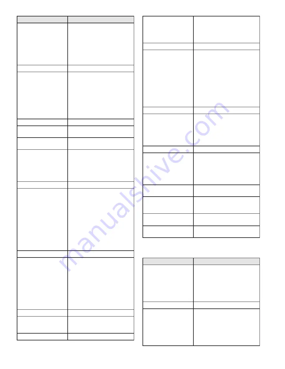
Screen
Description
SUPPLY 180
o
F
RETURN 150
o
F
This is the first screen that appears
after pressing
>
, and shows the
actual temperatures measured
by the supply and return sensors.
NOTE: If the boiler is configured to
use a 0 – 10 volt input, the return
sensor is disabled and the second
line of the display will be blank.
Press v once.
CH SET 180
o
F
BURNER 120
o
F
The screen displays the current
central heating temperature set
point on the top line. NOTE: This
temperature set point may vary
from what was set in the boiler
settings if an outdoor sensor is used.
The actual temperature measured
by the burner sensor is displayed on
the bottom line.
Press v once.
CH DEMAND OFF
BOILER
This screen displays the central heat
demand set for the cascade system.
Press v once.
This screen appears only when the
boiler is set as a Master Boiler.
CAS SET 180
o
F
SYSTEM 112
o
F
This screen displays the cascade set
point (maximum 190
o
F) on the top
line. The system sensor reading is
on the second line. The control will
cascade the boilers up to this set
point depending on demand.
Press v once.
DHW SET 119
o
F
DHW 117
o
F
Displays
the
current
tank
temperature set point on the top line.
The actual temperature measured
by the tank or return sensor (7250P-
325) is displayed on the bottom line.
If a mechanical aquastat is used in
place of the recommended sensor,
the second line will display ‘OFF’
in place of the temperature if the
aquastat measures close to its set
temperature, or ‘ON’ if the aquastat
temperature is too low.
Press v once.
OUTDOOR 11
o
F
FLUE 95
o
F
The current outdoor temperature
is displayed on the top line. If there
is no outdoor sensor connected
to the boiler, this line will display
“OFF” in place of the temperature.
If the outdoor sensor is shorted,
this line will display “ON” in place
of the temperature. The second
line displays the current boiler flue
temperature.
Press v once.
FLAME 0.0uA
FAN SPEED 3497 RPM
This screen displays boiler flame
current on the top line. The second
line displays boiler fan speed.
Press v once.
0-10 V 0.0V
BOILER
The top line displays the voltage on
the optional input. This voltage is
only relevant if an external 0-10 volt
signal is being used to control the
boiler.
Press v once.
BUS COMM NO CONN
This display shows the status of
the communication bus between
multiple boilers. If in a single boiler
configuration, the display will
show ‘NO CONN’. In a multiple
boiler configuration, if this is the
Master Boiler and other boilers are
connected to the communication
bus and powered, this screen will
show the address of each boiler
connected to the bus.
Press v once.
POWER ON 0H
CH ON 0H
The top line indicates the amount of
hours the boiler has been powered
over its life. The second line indicates
how many hours the burner has
been on for central heat demand
over its life.
Press v once.
DHW ON 0H
GOOD IGNIT 1X
The top line indicates the hours the
burner has been on for hot water
demand over the boiler’s life. The
second line indicates how many
times the burner has successfully
ignited over the boiler’s life.
Press v once.
This screen appears only when the
boiler is set as a Master Boiler.
SYS CH ON 0H
SYS DHW ON 0H
This screen displays how many hours
the boiler has run to meet central
heat and DHW demand.
Press
>
once at any status
screen.
TEMPERATURE CONTROL
ANALOG SIG 0.2 V
Displays 0-10V status when 0-10V is
connected.
Table 22 - Boiler Control Status Menu Screens
The next ten screens display the last ten boiler lockout faults.
Press
v
to scroll through the faults from most recent to oldest.
Screen
Description
FAULT HISTORY 1
07/27/2009 Mo 5:19A
This screen displays the most recent
boiler control lockout fault. The
top line will alternate between the
words ‘FAULT HISTORY’ and the
fault code encountered. The bottom
line displays the date and time the
fault occurred.
Press v once.
FAULT HISTORY 2
08/28/2009 Fr 5:19A
This screen displays the second
oldest boiler control lockout fault.
The top line will alternate between
the words ‘FAULT HISTORY’ and
the actual fault encountered. The
bottom line will display the date and
time that the fault occurred.
Содержание WBRE110
Страница 13: ...WHL 052 Rev 4 28 16 13 Figure 5 Boiler Dimensions NOTE All Dimensions Are Approximate ...
Страница 37: ...WHL 052 Rev 4 28 16 37 Figure 25 Internal Connection Diagram ...
Страница 62: ...WHL 052 Rev 4 28 16 62 Figure 30 Combustion System Replacement Parts 80 220kBTU Models ...
Страница 63: ...WHL 052 Rev 4 28 16 63 Figure 31 Combustion System Replacement Parts 299 399kBTU Models ...
Страница 64: ...WHL 052 Rev 4 28 16 64 Figure 32 Cabinet Replacement Parts All Models ...
Страница 65: ...WHL 052 Rev 4 28 16 65 Figure 33 Cabinet Replacement Parts All Models ...
Страница 72: ...WHL 052 Rev 4 28 16 72 Maintenance Notes ...