


WHL-052 Rev. 4.28.16
32
Figure 19 - Indoor and Outdoor Combustion Air - Single Pipe
I. Condensate Removal System
NOTE:
Check with your local gas company to determine if
combustion condensate disposal is permitted in your area. In
the state of Massachusetts, condensate must be neutralized
before entering a drain.
This boiler is a high efficiency appliance, and therefore produces
condensate: a by-product of the combustion process. A
condensate collection system with an internal float switch
monitors condensate level to prevent it from backing up into the
combustion system. There is a ¾” socket connection provided
to connect the outlet of the collection system to a drain or
condensate pump.
Condensate from the boiler is slightly acidic with a pH of 3.2
- 4.5. To avoid long term damage to the drainage system and
to meet local code requirements, Westinghouse recommends
neutralizing condensate with a Condensate Neutralizer Kit (Part
# 7450P-212 for 80/110/150/220/299/301 Models, Part # 7350P-
611 for 399 Models). The neutralizer kit connects to the drain
system and contains limestone chips that neutralize the pH
level of the condensate. The neutralizer kit should be checked
annually and the limestone chips replenished if necessary. When
replacing the limestone chips, take care to ensure chips are no
smaller than ½” to avoid blockage in condensate piping (refer to
Figure 20 for piping of the condensate neutralizer.)
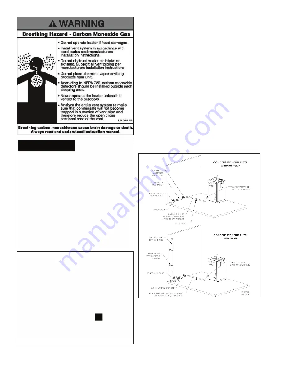
Figure 20 - Condensate Piping
NOTES:
1. Condensate line must be pitched at least ¼” per foot to
properly drain. If this cannot be done, or a very long length
of condensate hose is used, increase the condensate line to a
minimum of 1” ID and place a tee in the line after the condensate
neutralizer to properly reduce vacuum lock in the drain line.
2. PVC or CPVC pipe should be the only material used for
condensate line. Steel, brass, copper, and other metals will be
subject to corrosion or deterioration.
Содержание WBRE110
Страница 13: ...WHL 052 Rev 4 28 16 13 Figure 5 Boiler Dimensions NOTE All Dimensions Are Approximate ...
Страница 37: ...WHL 052 Rev 4 28 16 37 Figure 25 Internal Connection Diagram ...
Страница 62: ...WHL 052 Rev 4 28 16 62 Figure 30 Combustion System Replacement Parts 80 220kBTU Models ...
Страница 63: ...WHL 052 Rev 4 28 16 63 Figure 31 Combustion System Replacement Parts 299 399kBTU Models ...
Страница 64: ...WHL 052 Rev 4 28 16 64 Figure 32 Cabinet Replacement Parts All Models ...
Страница 65: ...WHL 052 Rev 4 28 16 65 Figure 33 Cabinet Replacement Parts All Models ...
Страница 72: ...WHL 052 Rev 4 28 16 72 Maintenance Notes ...