screws located at the corners of the
front panel, and pulling the panel for
ward.
2. The VU Meter (KS-8208 or 8218,
whichever was specified in the order)
is equipped with two 6.3-volt lamps.
These are connected in series in the
KS-8208
Meier. Remove the front cover
of the meter by removing the four
screws on the front of the case. Recon
nect the straps of the lamp sockets so
that the two lamps are connected in
parallel, and replace the front cover.
Remove the nuts and washers from the
four screws imbedded in the corners
in the back of the meter case. Attach
the meter to the panel from the front
using the four screws and nuts that
were removed. Connect the OR and
OR-RD wires to the large meter termi
nals, and the RD and GR-RD wires to
the two small terminals. It is not nec
essary to observe polarity in either
case.
3. Insert 2 Type 6J7 Vacuum Tubes in
the cushioned and center sockets, and
a type 6F6 Vacuum Tube in the re
maining socket.
4. Replace the rear cover of the unit and
fasten by turning the thumb screws in
the clockwise direction.
Power Unit
The AC Power Unit should be assembled
to the shelf in the upper part of the power
unit carrying case by means of the four
screws and stop nuts supplied. One type 80
rectifier is required and must be ordered sep
arately. The power cord and wall plug are
not supplied and should be made up to suit
operating conditions.
Battery Equipment
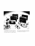
The 22E Speech Input Equipment power
supply carrying case is designed for opera
tion either with batteries or with the ESR-
610199 AC Power Unit or both.
The B-147071 Set of Accessories for bat
tery operation contains all the accessories,
excepting batteries (listed above) that are
6
necessary to modify the carrying case. Full
instructions for battery operation are fur
nished with the 22E Speech Input Equipment
when ordered for battery operation.
Setting Up
for
Operation
Microphones
The microphones should be connected
through the associated cables to the desired
Cannon receptacle at the left end of the unit.
Each microphone receptacle is numbered to
correspond with the associated mixing poten
tiometer. The shield of the microphone cord
should be connected to Pin No. 3 of the plug.
Program Line and Order Wire
The program line and the order wire, or
spare program line, are connected to the
terminals marked "LINE 1" and "LINE 2"
at the right hand end of the unit.
With a screwdriver, set the output im
pedance switch D4 to "150" or "600" to cor
respond with the desired output impedance
of the amplifier.
Order Wire Telephone Set
The order wire telephone set can either
be connected to the terminals marked "TEL"
or plugged into the jack marked "TEL".
Monitoring Headsets
One or two pairs of Western Electric
1002F Headsets or the equivalent equipped
with Western Electric 47 A Plugs, or equiva
lent, should be plugged into the jacks marked
"Monitor". Where loudspeaker monitoring
is desired, or where sound reinforcement is
wanted, a Western Electric 124E or 142A
Amplifier equipped with a suitable bridging
input
coil
may
be connected to
one of
the
monitor jacks or bridged across the line.
Ground
The terminal marked "GND" should be
connected to a good electrical ground.
Battery Connections
Internal connections of the batteries in
the carrying case are described in the in-


