background image


WRD


Manuale utente


EN


3. MENU NAVIGATION 

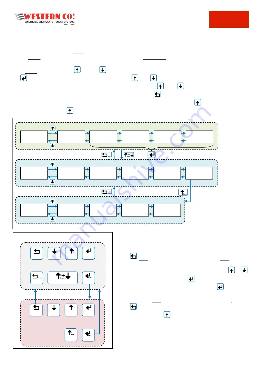
Navigating through the various screens is very simple and intuitive. The WRD has two display environments (

Pic.2

): 

-


the main environment MAIN, consisting of six screens where the operation of the system is monitored; 

-


SETUP setting environment, consisting of 6 s 5 in ADV. SETUP where the settings for the operation are 
set. 

In the MAIN environment, the 

 UP and  

 DOWN buttons are used to scroll through the screens from 1.0 to 6.0, 

the 

  ENTER button accesses any submenu. Pressing the 

 UP / 

 DOWN buttons simultaneously for 1 sec. you 

access the SETUP environment. Here, it is always repeated with the same 


UP or 

  DOWN buttons, the scrolling of 

the screens from 7.0 to 7.5. To return to the MAIN environment use the 

 ESC button pressed for 1 sec.  

To enter ADV. SETUP select the "Advanced Setup" item on the 7.5 OTHERS screen, press the 

 UP botton so that "-->" 

appears and then press the 

 OK button for 1 sec. 


It  is  possible  to  enter  the  EDIT  mode  (

Pic.3

),  where  it  is 

allowed, to modify the parameters by keeping pressed the 

  EDIT  button  for  1  sec.  Entry  into  the  EDIT  mode  is 

visible on the display by the presence of the cursors on the 

modifiable  parameter.  For  editing  are  used  the 

  / 


INC/DEC  buttons,  press  the 

  SELECT  button  to  change 

the value. For 

save the changes the

 button 

  SAVE must 

be kept pressed for 1 sec. 
To exit the EDIT mode, 

without saving the changes

, use the 

    ESC  button.  To  confirm  the  items  that  require  an 

action, press the 


OK button for 1 sec. 


SETUP 

MAIN 

3.0 

VARIABLES


2.0 

MAIN B


1.0 

MAIN A


4.0 

PV STRINGS


5.0 

ENERGIES


6.0 

LOG.EVENTS


7.1 

DATA/TIME


7.0 

SYSTEM


7.2 

DATA LOGGER


7.3 

NETWORK


7.4 

INFO


7.5 

OTHERS


ADV. SETUP 

8.1 

WBM


8.0 

WBUS CONFIG


8.2 

WRMxx


8.3 

W-INVERTER


Navigation Menu 


8.4 

WRD


submenu 


NAVIGATION MODE 


DOWN 


UP 


EDIT


ESC


> EDIT MODE < 


ESC EDIT 


DEC 


INC 


SELECT 


OK 


SAVE 


GO INTO SETUP 


--- 


--- 


Keys mode 

Pic.2 - Navigation menu 

Pic.3 - Edit menu 

Содержание WRD

Страница 1: ...WRD Remote display for WESTERN WRD SYSTEM Manuale utente User manual DĂŶƵĞů ĚĞ ů ƵƚŝůŝƐĂƚĞƵƌ Manual del usuario Benutzerhandbuch IT DE ES FR EN ...

Страница 2: ...th the various compatible devices able to access all the parameters both for the display and for the management of the control functions The simple user interface with 128x64 display and 4 buttons allows an immediate visualization of all the parameters powers voltages charge and PV string currents energy meters data logger and events From WRD all Setup settings can be made for each single WRMxx co...

Страница 3: ...FEATURES 6 5 MECHANICAL DIMENSIONS 6 6 FIXING OPTIONS 7 7 IOT PLATFORM FOR MONITORING AND REMOTE CONTROL 8 8 CONFIGURATIONS 9 8 1 Configuration WRD WBM 9 8 1 1 Description 9 8 1 2 Main screens 9 8 2 Configuration WRD WRMxx 1 8 9 8 2 1 Description 9 8 2 2 Main screens 9 8 3 Configuration WRD WBM WRMxx 1 8 10 8 3 1 Description 10 8 4 Configuration WRD Leonardo System 10 8 4 1 Main screens 10 9 MAIN ...

Страница 4: ...net cloud is optional The WESTERN WRD SYSTEM must be configured by setting to each WRMxx controller a unique address from 1 to 32 while the WBM already has a fixed address 33 as in the case of connection with a Leonardo 34 2 1 Installation procedure 1 To install the WRD in a dry place there are two fixing options from the panel and with frame Pic 4 2 At the back you can access the electrical conne...

Страница 5: ...sources The screens for each configuration are described below 2 3 System Setup In the menu 7 0 SYSTEM the system settings are executed the list of parameters changes according to the current configuration Detailed explanations are described in the chapter Configurations 2 4 Date Time Setup In the menu 7 1 DATE TIME you set the system clock and the time zone Timezone It is important to correctly s...

Страница 6: ... 7 5 OTHERS screen press the UP botton so that appears and then press the OK button for 1 sec It is possible to enter the EDIT mode Pic 3 where it is allowed to modify the parameters by keeping pressed the EDIT button for 1 sec Entry into the EDIT mode is visible on the display by the presence of the cursors on the modifiable parameter For editing are used the INC DEC buttons press the SELECT butt...

Страница 7: ...autodetect V Supply voltage range Vbatt 10 64 V Self consumption Pq 1 0 W Operating temperature Tamb 10 40 C Max cable section terminal Power and RS485 1 5 mm2 Weight 250 g Dimension LWH 160 x 95 x 27 mm Degree of protection IP20 Tab 1 Electrical features 5 MECHANICAL DIMENSIONS Pic 4 Mechanical dimensions ...

Страница 8: ...WRD Manuale utente EN 7 6 FIXING OPTIONS Pic 5 Fixing options ...

Страница 9: ... display time period x Reports of events related to the system such as alarms or useful information x Specific information of the system installed type capacity and battery voltage device firmware versions Pic 6 WEB Client Access to the portal The first time you log in to the WRM MONITOR interface you need to register Registration is carried out at the following link also valid for subsequent acce...

Страница 10: ...d overvoltage Setting the thresholds for the Charge contact it can also be controlled according to the SoC in case some applications require it 8 1 2 Main screens In the following picture are described the graphic used in the various screens of the main menu Take into account the notes shown in the pictures 8 2 Configuration WRD WRMxx 1 8 8 2 1 Description This configuration is used in a stand alo...

Страница 11: ...t can also be controlled according to the SoC in case some applications require it Considering that in CONTROLLER mode the charge made by the WRMxx is already controlled through the WBUS it is not necessary to exploit the Charge contact of the WBM The WRMxx controllers which can be paralleled up to a maximum of 8 are used to charge the battery See dedicated product manual for more details The WRD ...

Страница 12: ...tatus bar System voltage Battery temperature Flash if out range System control in progress PAUSE pause charge Low voltage battery Battery voltage Flash if out range Phase of charge Bulk Abs Float End of charge voltage Battery voltage meter Status bar System voltage Battery temperature Flash if out range State of charge2 if not yet valid Flash if out range Battery power IN OUT Flash if out range Cu...

Страница 13: ... Reset WBM counters2 n Menu Warning Date of Reset WRM counters1 Battery output counter from Reset MENU 4 0 PV A string PV B string n Menu Warning PV string voltage1 PV string current1 PV string power1 PV input displayed internal temperature PV input hardware Flash if over Temp MENU 3 0 Battery current IN OUT Flash if out range Photovoltaic variables Battery voltage Flash if out range Battery varia...

Страница 14: ...10 2000Ah battery bank capacity to compute SoC 2 10 8 12 56V below this threshold the LOAD output is activated 1 24h 24h LOAD output always active 1 1 16h LOAD output active from sunset for the set hours 1 Only Night LOAD output active only during the night 1 Only Day LOAD output active only during the day 1 OnSurPlus LOAD output active only during an energy surplus 1 List displayed Settable value...

Страница 15: ...If there is no card show NOT PRESENT and no information is available uSD CARD read the type of file system NONE FAT12 16 32 and calculates the free space on the card FIND WRD read and list the files one at a time by showing the name size and date of the last update At the end shows END LIST SAMPLE EVENT show the remaining time for the next sampling List displayed Settable value and descriptions Va...

Страница 16: ...NS 008 1 secon DNS 255 2 secon DNS 255 3 secon DNS 255 4 secon DNS 255 OFF ON Disable Enable cloud connection to transfer data to the server 0 255 set the device IP Address 0 255 0 255 1 255 DHCP set the Network Setup automatically the other values will be ignored 0 255 set the subnet mask 0 255 0 255 0 255 0 255 set the Gateway IP Address 0 255 0 255 0 255 0 255 set the primary DNS IP Address 0 2...

Страница 17: ... 0 0 WRMxx n 4 0 0 WRMxx n 5 0 0 WRMxx n 6 0 0 WRMxx n 7 0 0 WRMxx n 8 0 0 W INVERTER 0 0 U I Mode Basic OFF LINE ON LINE current status of cloud connection List Settable value and descriptions Value firmware revision of the WRMxx devices from 1 to 8 0 0 if device is not present current device IP Address current subnet mask current Gateway IP Address current primary DNS IP Address current secondar...

Страница 18: ...nuale utente EN 17 Configuration with WRD WBM WRMxx 1 8 00 33 WBUS Address of the WBM device 0 32 WBUS Address of the WRMxx devices from 1 to 8 00 if device is not present 00 34 WBUS Address of the WI device ...

Страница 19: ...FF disch 1 Ļ 25 ON disch 1 Ĺ 40 OFF charge 2 Ĺ 100 ON charge 2 Ļ 90 UPDATE FW 10 2000Ah battery bank capacity to compute SoC 2 List displayed Settable value and descriptions Value RUN CAUTION starts the procedure to update the firmware in the WBM device The firmware update file must be present in the uSD card 2 0 ON disch below this threshold the ALARM output 1 is activated Discharge OFF 2 OFF dis...

Страница 20: ...5 12V 48 00 50 24V below this threshold the WRM30 goes into Low Battery status and deactivates the LOAD 1 24h 24h LOAD always active 1 1 16h LOAD active from sunset for the set hours 1 Only Night LOAD active only during the night 1 Only Day LOAD active only during the day 1 OnSurPlus LOAD active only during an energy surplus 1 1 8h time in Absorption phase before moving to Float phase 1 List displ...

Страница 21: ...tem is set to the Genset value it defines the power necessary to charge the battery pack Defines the use of the MeterPort Port not used PV Pulse Used in case of system with AC configuration to connect the counter of photovoltaic production Genset By jumpering this port with the AUX1 input using the cable supplied it is possible to control the ignition of a generator when the battery percentage fal...

Страница 22: ...F RESET RUN UPDATE FW RUN Tech Menu Psw 00 RUN Reset the WRD device List displayed Settable value and descriptions Value 0 FF password to access the Technical Menu CAUTION Technical Menu is reserved for factory checks RUN CAUTION starts the procedure to update the firmware in the WRD device The firmware update file must be present in the uSD card To start WKH SURFHGXUH SUHVV ERWK Ĺ DQG Ļ NH V auto...

Страница 23: ... or other interventions different by the instructions supplied by us The warranty is not valid also in case of damages coming from transport and or incorrect storage of the product force majeure or catastrophic events frost fire floods lightning vandalism etc All of the above mentioned guarantees are the sole and exclusive agreement which supersedes any proposal or agreement oral or written and an...

Страница 24: ...WRD Manuale utente A IT DE ES FR EN Appendice Appendix Annexe Apéndice Anhang ...

Страница 25: ......

Страница 26: ......

Страница 27: ......

Страница 28: ......

Страница 29: ......

Страница 30: ......

Страница 31: ......

Страница 32: ...ciété WESTERN CO Srl Tous droits réservés La reproduction et l utilisation des informations contenues dans le présent document sont interdites sans l autorisation écrite de WESTERN CO Srl Este documento es de propriedad de WESTERN CO Srl Todos los derechos reservados La reproducción y el utilizo de las informaciones contenidas en este documento son prohibidos sin el consenso de WESTERN CO Srl Dies...

Страница 33: ......

Отзывы: