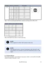
A1 to A4 are used for WLAN Wave 2 communication at 5 GHz. At least A1 must be
connected to an external WLAN antenna if Wave 2 module is used. The antenna
configuration is made through the software interface.
B1 and B2 are used for WLAN Wave 1 communication at 2.4 GHz/5 GHz. At least B1
must be connected to an external WLAN antenna if Wave 1 module is used. The antenna
configuration is made through the software interface.
NOTICE
Any unused antenna ports must be properly terminated with 50 Ohm,
otherwise the product might be damaged when power is applied to a non-
terminated antenna port.
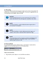
NOTE
To ensure specified IP protection, suitable QMA connectors/cables and
terminations must be used.
3.5. LED Indicators
DC
OPR
ERR
X1
X2
Figure 5. LED indicators
LED
Description
DC
Power status
OPR
Operation status
ERR
Error status
X1
Ethernet status for X1 port
X2
Ethernet status for X2 port
Table 9. LED indicators
NOTE
Refer to management guide for detailed LED status indication.
3.6. Dimensions
Dimensions are stated in mm and are regardless variants.
16
Ibex-RT-610 Series

