Equipment Issue 2
030-101674 Rev. A, March 2008
Section DSA-WM2-140-202
R
E
Copyright 2008 Westell, Inc. All rights reserved.
Westell
R
and 200 MECHANICS
R
are registered trademarks of Westell, Inc.
0803I2RA
DSAWM-214ALCI2 14-Slot Digital Shelf Enclosure
CONTENTS
PAGE #
1. GENERAL
. . . . . . . . . . . . . . . . . . . . . . . . . . . . . . . . . . . .
2. FEATURES
. . . . . . . . . . . . . . . . . . . . . . . . . . . . . . . . . . .
3. INSTALLATION
. . . . . . . . . . . . . . . . . . . . . . . . . . . . . . .
4. OPTIONS
. . . . . . . . . . . . . . . . . . . . . . . . . . . . . . . . . . . .
5. TESTING & TROUBLESHOOTING
. . . . . . . . . . . . . .
6. CUSTOMER & TECHNICAL SERVICES
. . . . . . . . .
7. WARRANTY & REPAIRS
. . . . . . . . . . . . . . . . . . . . . .
8. SPECIFICATIONS
. . . . . . . . . . . . . . . . . . . . . . . . . . . .
1.
GENERAL
1.1
Document Purpose
This document describes the Issue 2 DSAWM-214ALC wall-
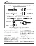
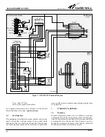
mount Digital Shelf Enclosure, shown in Figure 1. See Figure 2
for an application and circuit overview. See Table 5 for specific
models and ordering information.
- NOTE -
Hereafter, the DSAWM-214ALC Issue 2 digital shelf enclosure
also may be referred to as the DSAWM-214" or enclosure."
1.2
Document Status
This practice replaces practice number 030-101322 for the
DSAWM-214ALC Issue 2 product. The 030-101322 practice
replaced practice number 057-033700. The Issue 2 equipment
adds the redundant powering capability and complies with
UL1950 requirements. Whenever this practice is updated, the
reason will be stated in this paragraph.
1.3
Product Purpose
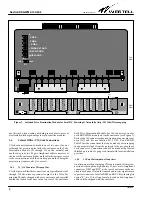
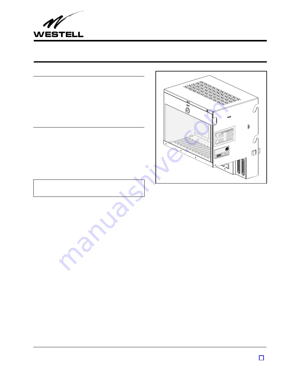
The DSAWM-214 enclosure houses up to fourteen 200 ME-
CHANICS
R
-type (or seven 400-type) plug-in modules which
are designed for use in 1.544 Mb/s Hi-Capacity Digital Services
(HiCap) or High-bit-rate Digital Subscriber Line (HDSL) ap-
plications. Central Office (CO) side connections are made via
wirewrap pins mounted on the plug-in
Telco Termination Mod-
ule
located at the top of the enclosure or via two 50-pin
Amphenol-type connectors (at the top rear of enclosure). Cus-
tomer side connections are made through either the two
RJ48H D-connectors or through the RJ48C jacks (depending
on the specific model used), all located on the lower part of the
front of the enclosure. To power the modules in the shelf, either
span power, local -48 VDC power, or AC power is used. Local
-48 VDC power is applied to a screw terminal block on the
Telco
Termination Module
supplied with the enclosure. An optional
Westell 2555 120 VAC to -48 VDC Power Supply
provides local
DC powering.
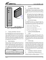
Figure 1. Isometric View of DSAWM-214 Enclosure
1.4
Product Mounting
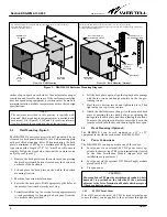
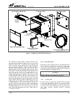
The DSAWM-214 enclosure is typically mounted on a wall.
Rack mounting is possible using rack-mount kits (see
Figure 3).
2.
FEATURES
The DSAWM-214 offers the following features.
D
NEBS certified
D
Meets UL 1950/CSA requirements
D
Wall mounting with removable, rear, wall-mount plate
with two top keyhole slots for easy mounting
D
Optional relay rack mounting ears 080-500455
D
Accepts local AC or DC powering or span powering
D
Features 14 positions which can accept either of the fol-
lowing module arrangements:
S
Up to 14 high-density, 200 MECHANICS
R
-type, NIU
modules, plus one power supply module
S
Up to seven 400-type NIU/HDSL modules, plus one
power supply module
D
Central Office side (Network/Facility) connections can be
made via either the 6-pin wirewrap connectors on the
plug-in Telco Termination Module installed at the top of


