Section DSA-WM2-140-202
030-101674 Rev. A
R
2
0803I2RA
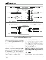
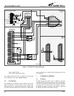
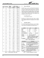
the unit or via the XMT and RCV 25-pair Amphenol-type
male connectors at the rear of the enclosure
D
Customer side connections made via either the two
RJ48H D-connectors or the modular RJ48C jacks, all lo-
cated on the lower front of the enclosure
D
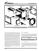
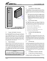
Removable, tinted, front door allows visual monitoring of
module LEDs
D
Keyed front door locking mechanism provides security
D
Static wrist-strap jack at front of unit for Electrostatic Dis-
charge (ESD) protection
D
Totally grounded enclosure with chassis ground lug at bot-
tom front of enclosure
D
Top and bottom heat ventilation and convection holes
D
Circuit Assignment Card facilitates easy module identifi-
cation and assignment
D
Strategically-placed cable tie-downs for efficient, neat,
cable management
D
Enclosure chassis and interior frame all heavy gauge steel
for strength, durability, and longevity
Telco Termination Module (Local DC/GND)
D
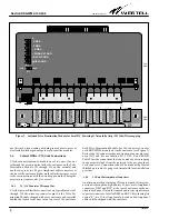
Terminal Block (TB1) for local DC power and ground con-
nections
D
S1 Slide Switch for THRU" or OPEN" for selecting ei-
ther an open or through shield ground from TB1
D
Fourteen 6-pin wirewrap connectors, J1 through J14 (one
for each slot), at front of Telco Termination Module pro-
vide termination points for CO-side cable wires when
using 200-type cards
D
Front panel ALARM LED lights when fuse is blown
D
Front panel fuse rated at 2 amps
Optional AC Power Supply
D
Accepts optional local AC powering (Westell model 2555)
in the 15th slot
3.
INSTALLATION
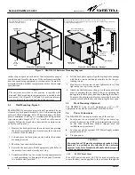
Installation consists of examining some pre-mounting con-
cerns, physically mounting the enclosure (back plate) on a wall,
making the necessary electrical, power, ground, and signal
cable connections, and installing the DNI or HDSL modules in
the enclosure. The following paragraphs provide detailed in-
structions for performing these procedures.
3.1
Pre-Mounting Considerations
Before installing the enclosure, visually inspect the unit for
damages, follow proper safety and ESD precautions and proce-
dures, evaluate and determine the proper mounting
application, installation personnel, and installation environ-
ment (mechanical, thermal, electrical), and gather the
required mounting tools, mounting hardware, and test equip-
ment.
The DSAWM-214 enclosure should be installed by authorized
trained personnel only. In accordance with UL 1950, this
mounting enclosure is suitable for mounting on concrete or
other noncombustible surfaces only. It is also recommended
that adequate horizontal and vertical space be left between
multiple installations to allow for proper cable access and ven-
tilation. The distance from the cable entry point should be
consistent with local installation practices.
- NOTE -
Visually inspect the equipment for damage at the time of delivery:
if damaged in transit, immediately report the damage to the
transportation company and Westell.
- CAUTION -
- Never install telephone wiring and/or telephone equipment
during a lightning storm.
- Never install telephone jacks in wet locations unless the
jack is specially designed for wet locations.
- Never touch uninsulated telephone wires or terminals
unless the telephone line has been disconnected at the
network interface.
- Always use caution when installing or modifying telephone
equipment.
- All wiring should be done by a certified technician using
only approved telephone wire.
3.1.1
Considering Safety
When using and installing telephone/telecommunications
equipment, basic safety instructions should always be followed
to reduce risk of fire, electric shock, and injury to people and
equipment, including the following:
Important Safety Instructions (Please Save)
A.
Read and understand all instructions.
B.
Follow all warnings and instructions marked on product.
C.
Do not place this product on an unstable cart, stand, table or other
unstable surfaces: the product may fall, causing serious damage to
product.
D.
Slots and openings in the product are provided for ventilation. To
protect it from overheating, these openings must not be blocked or
covered. This product should never be placed near or over a radia-
tor or heat register. This product should not be placed in a built-in
installation unless proper ventilation is provided.
E.
This product should be operated only from the type of power
source indicated on the marking label.
F.
Never push objects of any kind into this product through product
slots as they may touch dangerous voltage points or short out parts
that could result in the risk of fire or electrical shock. Never spill liq-
uid of any kind on the product.
G.
Perform ground connections prior to power connections.
H.
Follow and use proper Electrostatic Discharge (ESD) precautions
and procedures.
3.1.2
DC Powering & Heat Release Considerations
T1 NIU modules and HDSL HRU modules in the DSAWM-214
enclosure can be either line/span powered remotely from a Cen-
tral Office (CO) or locally powered via either a
Telco Termination
Module
(and a -48 VDC power source) or from a plug-in AC
power supply.
3.1.2.1
Line Powering Mode
When these modules are utilized in a line power mode, the -48
V battery should not be connected to the enclosure. The HDSL


