Section DSA-WM2-140-202
030-101674 Rev. A
R
10
0803I2RA
Typical Slot
2
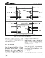
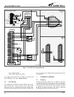
Figure 9. DSAWM-214 Functional Diagram
Connector Pins
55
56
49
47
41
35
27
17
15
13
7
5
1
-48 V
XMT
R1
T1
1
26
R
T
1
26
See Table 3
See Table 3
CKT
Chassis
Ground
GND
(male)*
(male)*
Facility
Facility
(Rear View)
8
NC
NC
NC
NC
3
7
6
RJ48C Jack
J1- J14
1
2
5
4
1
2
5
4
(Female)
See Table 5
T
R
T1
R1
26
1
25
50
14
39
39
14
5
15
T1
R1
RJ48H
(female)
J15
55
49
15
5
-PWR A
+PWR A
+PWR B / CKT GND
CHASSIS GND
SHIELD GND
SHIELD GND
CHASSIS GND
CKT GND
F1 (2 Amp)
-48 V
ALARM
J1 - J7
Wirewrap Pins
Telco Termination Module
SGND
R1
R
T
47
41
RCV
13
7
T
O
S1
P
E
N
H
R
U
SHIELD
GND
(IN)
(OUT)
* Amphenol
TB1
Zero Ohm Resistor
11
T1
-PWR B
D1
D2
26
1
25
50
1
26
39
14
55
49
T
R
J16
Voice: (800) 377-8766
email:
For additional information about Westell, visit the Westell
World Wide Web site at http://
6.2
Part Numbers
This equipment is identified by a product number and an issue
number. Each time a change is made to the product which
changes the form, fit, or function of the product, the issue num-
ber is incremented or advanced by one. Be sure to indicate the
issue as well as the model number when making inquiries about
the equipment.
7.
WARRANTY & REPAIRS
7.1
Warranty
Westell warrants this product to be free of defects at the time
of shipment. Westell also warrants this product to be fully func-
tional for the time period specified by the terms and conditions
governing the sale of the product. Any attempt to repair or
modify the equipment by anyone other than an authorized
Westell representative will void the warranty.


