


PS71090 Product Manual
March 2017, Rev G
WESTELL.COM
©2017 Westell Technologies
March 2017; Doc No. CS14702802UM rG
1.877.844.4274
Page 30 of 50
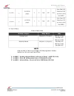
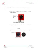
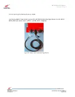
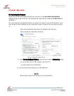
4.
Connect the 9 position D-Sub connector at one end of the serial cable to the
Alarm Relay connector on the PS71090, Figure 5-6. Be sure to fasten the
connector screws securely.
Figure 5-5:
Alarm Relay Cable Connected to Signal Booster
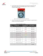
5.
Connect the stripped end of the serial cable to the alarm relay panel. Refer to
Table 5-1 for connection information.
Table 5-1: Alarm Relay Connections
Pin
Number
Contact Type
Conductor Color
(supplied Cable)
Alarm Number
1
NC
(Normally Closed)
Black
Alarm One
2
NO
(Normally Open)
Brown
Alarm One
3
CC
(Common Connection)
Red
Alarm One
4
NC
(Normally Closed)
Orange
Alarm Two
5
NO
(Normally Open)
Yellow
Alarm Two
6
CC
(Common Connection)
Green
Alarm Two
7
NC
(Normally Closed)
Blue
Alarm Three
8
NO
(Normally Open)
Violet
Alarm Three
9
CC
(Common Connection)
Grey
Alarm Three
White
Unused


