background image

6

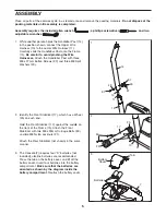
6. Press the Side Shield Cover (40) onto the Left and

Right Side Shields (1, 2). Make sure that the four
tabs (A) on the Side Shield Cover snap into the Side
Shields.

Insert the Seat Post (20) into the Frame (15), and
press the Seat Post Bushing (23) down into the
Frame. Next, align one of the holes in the Seat Post
with the hole in the Frame. Insert the Seat Knob
(29) into the Frame and the Seat Post, and tighten
the Seat Knob into the Frame. 

Make sure to insert

the Seat Knob through one of the holes in the
Seat Post; do not insert the Seat Knob under the
Seat Post. 

Attach the Seat (19) to the Seat Post (20) with four

M8 Nylon Locknuts (21) and four M8 Split Washers
(49). Note: The Nylon Locknuts and Split Washers
may be pre-attached to the bottom of the Seat.

4. Connect the wire harness on the Handlebar (5) to

the indicated wire harness on the Console (7). Insert
both wire harnesses into the opening in the bottom
of the Console. Then, insert the metal tube on the
Handlebar into the opening in the bottom of the
Console. 

Be careful not to pinch the wire har-

nesses.

See the inset drawing. Tighten an M4 x 16mm
Screw (9) into the indicated bracket on the Console
(7) and into the metal tube on the Handlebar (5).

Snap the bookrack onto the Console (7) in the loca-
tion shown.

6

A

1

2

40

15

20

21

23

21

49

49

19

29

5

7

Metal Tube

Wire Harness

5

7

9

Bracket

Bookrack

5. While another person holds the Console (7) in the

position shown, connect the wire harness on the
Console to the Upper Wire Harness (10). Insert the
excess wire harness into the Handlebar Post (14).

Attach the Console (7) to the Handlebar Post (14) with
three M10 x 27mm Button Screws (8) and three M10
Split Washers (41). 

Be careful to avoid pinching the

wire harnesses.

5

7

10

8

8

14

Wire Harness

41

41

8

Be careful

to avoid

pinching

the wire

harnesses.

4

Содержание Pursuit E40 Bike

Страница 1: ...ng complete customer satisfaction If you have questions or if there are missing parts we will guarantee complete satisfaction through direct assistance from our factory TO AVOID DELAYS PLEASE CALL DIRECT TO OUR TOLL FREE CUSTOMER HOT LINE The trained technicians on our cus tomer hot line will provide imme diate assistance free of charge to you CUSTOMER HOT LINE 1 866 699 3756 Mon Fri 6 a m 6 p m M...

Страница 2: ...ot protection 8 When adjusting the seat insert the seat knob through one of the holes in the seat post see the drawing on page 3 Do not insert the seat knob under the seat post 9 Always keep your back straight when using the exercise cycle Do not arch your back 10 If you feel pain or dizziness while exercising stop immediately and begin cooling down 11 The pulse sensor is not a medical device Vari...

Страница 3: ...oll free at 1 866 699 3756 Monday through Friday 6 a m until 6 p m Mountain Time excluding holidays To help us assist you please mention the product model number and serial number when calling The model number is WLEX19840 The serial number can be found on a decal attached to the exercise cycle see the front cover of this manual for the location of the decal Before reading further please look at t...

Страница 4: ...u assemble the exercise cycle use the drawings below to identify the small parts needed for assembly The number in parenthesis below each drawing is the key number of the part from the PART LIST on page 14 The number following the parenthesis is the quan tity needed for assembly Note Some small parts may have been pre assembled If a part is not in the parts bag check to see if it has been pre asse...

Страница 5: ...lebar Post with three M8 x 27mm Button Screws 37 and three M8 Split Washers 49 1 2 17 25 25 15 30 21 14 37 37 37 49 15 49 10 11 3 The Console 7 requires four D batteries not included alkaline batteries are recommended Press the tab on the battery cover and lift off the battery cover Insert four batteries into the battery compartment Make sure that the batteries are oriented as shown by the diagram...

Страница 6: ...5 to the indicated wire harness on the Console 7 Insert both wire harnesses into the opening in the bottom of the Console Then insert the metal tube on the Handlebar into the opening in the bottom of the Console Be careful not to pinch the wire har nesses See the inset drawing Tighten an M4 x 16mm Screw 9 into the indicated bracket on the Console 7 and into the metal tube on the Handlebar 5 Snap t...

Страница 7: ... console can be operated four D batteries must be installed If you have not installed batteries see assembly step 3 on page 5 19 20 40 29 7 Identify the Left Pedal 28 there is an L on the Left Pedal for identification Using an adjustable wrench firmly tighten the Left Pedal counter clockwise into the left arm of the Crank 33 Tighten the Right Pedal not shown clockwise into the right arm of the Cra...

Страница 8: ...of measurement hold down the On Reset button for six seconds The display mode indicators see B at the right will show which unit of mea surement is selected When the batteries are replaced it may be necessary to reselect the desired unit of measurement B Display mode indicators These indicators show which display mode is currently shown scan speed time distance resistance level calories fat calori...

Страница 9: ...the resistance level changes the console will show the resis tance level for six seconds When a personal trainer program is selected the display will show the time remaining in the program instead of the elapsed time If desired you can select a sin gle mode for continuous dis play Press the Display Mode button repeatedly until only the MPH or Km H Time Miles or Kms Resist Cals or Fat Cals indicato...

Страница 10: ...r each period The same resistance setting may be programmed for two or more con secutive periods During the program the resistance of the pedals will automatically change as shown by the applic able profile on the console If the current resis tance level is too high or too low you can change the resistance level by pressing the and but tons However when the current period of the program ends the r...

Страница 11: ...switch wire HOW TO ADJUST THE REED SWITCH If the console does not display correct feedback the reed switch should be adjusted To adjust the reed switch you must first remove the Left Side Shield 1 see the drawing at the top of this page Using an adjustable wrench turn the Left Pedal 28 clockwise and remove it from the Crank 33 Remove the two M4 x 16mm Screws 9 and three M4 x 38mm Self tapping Scre...

Страница 12: ...e it Remove the right side shield Press down on the center of the Belt 16 between the front and rear sprockets There should be from 1 4 to 3 4 of ver tical movement in the center of the Belt If the Belt 16 is properly adjusted reattach the side shields and pedals If the Belt needs to be adjusted loosen the M8 Washer Nut 37 on each side of the Flywheel 32 To tighten the Belt turn the two M6 Stop Nu...

Страница 13: ... exercise must be aerobic Aerobic exercise is activity that requires large amounts of oxygen for prolonged periods of time This increases the demand on the heart to pump blood to the muscles and on the lungs to oxygenate the blood For aerobic exercise adjust the intensity of your exercise until your heart rate is near the highest number in your training zone WORKOUT GUIDELINES Each workout should ...

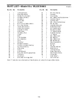
Страница 14: ... 2 Wheel Hub 25 2 Wheel 26 2 Wheel Spacer 27 2 M6 x 16mm Self tapping Screw 28 1 Left Pedal 29 1 Seat Knob 30 4 M8 x 90mm Carriage Bolt 31 1 M10 Flat Washer 32 1 Flywheel 33 1 Crank Pulley 34 3 M4 x 38mm Self tapping Screw 35 1 Flywheel Spacer 36 1 Flywheel Axle 37 3 M8 x 27mm Button Screw 38 2 M6 Eye Bolt 39 2 Adjustment Bracket 40 1 Side Shield Cover 41 3 M10 Split Washer 42 1 Bearing Assembly 4...

Страница 15: ...9 24 25 26 27 15 16 24 25 26 27 21 38 56 51 39 28 33 13 33 30 50 9 21 21 21 48 32 46 21 43 55 30 18 44 44 36 35 45 17 49 49 40 42 9 42 21 47 38 39 47 47 34 34 57 31 8 41 8 41 37 9 4 4 10 11 53 54 12 52 21 49 58 21 EXPLODED DRAWING Model No WLEX19840 R0604A 15 ...

Страница 16: ...ble to freight damage abuse mis use improper or abnormal usage or repairs not provided by an ICON authorized service center products used for commercial or rental purposes or products used as store display models No other warranty beyond that specifically set forth above is authorized by ICON ICON is not responsible or liable for indirect special or consequential damages arising out of or in con n...

Отзывы: