background image

10

DESCRIPTION OF THE CONSOLE 

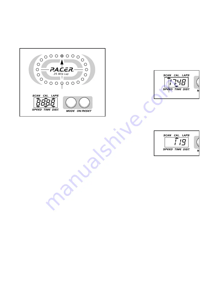
The console is designed to help you get the most
from your workouts. As you exercise, you can watch
your progress around the LED track, while the 
display provides continuous exercise feedback. 
The six modes of the display are described below.

Speed—This mode displays your current exercise
speed, in miles per hour.

Time—This mode displays the length of time you
have exercised. Note: If you stop exercising, the time
mode will pause until you resume.

Distance—This mode displays the total distance you
have completed, in miles. 

Laps—This mode displays the number of 1/4-mile
laps you have completed around the LED track. 

Calorie—This mode displays the approximate number
of Calories you have burned.  

Scan—This mode displays the speed, time, distance,
laps, and calorie modes, for 5 seconds each, in a
repeating cycle.

BATTERY INSTALLATION

Before the console can be operated, two “AA” batter-
ies must be installed. If you have not installed batter-
ies, see assembly step 10 on page 8. 

HOW TO OPERATE THE CONSOLE

If there is a thin sheet of clear plastic on the face of
the console, remove it.

1. To turn on the power, press the on/reset button or

simply begin exercising. When the power is turned
on, one LED indicator will light in the LED track,
and the entire display will appear for two seconds.
The console will then be ready for operation.  

2. Select one of the five modes:

Scan mode—
When the power
is turned on, the
scan mode will
automatically be
selected. One
mode indicator
will show that the
scan mode is selected, and a flashing mode indica-
tor will show which mode is currently displayed.
Note: If a different mode is selected, you can
select the scan mode again by repeatedly pressing
the mode button.

Speed, time,
distance, laps, 
or calorie mode—
To select one of
these modes for
continuous 
display, press the
mode button repeatedly. The mode indicators will
show which mode is selected. (Make sure that the
scan mode is not selected.)   

3. The LED track represents a distance of 1/4 mile. As

you exercise, the indicators around the track will
light one at a time until you have completed 1/4
mile. A new lap will then begin.

4. To reset the display, press the on/reset button.

5. To turn off the power, simply wait for about four

minutes. Note: The console has an “auto-off”
feature. If the pedals are not moved and the
console buttons are not pressed for four 
minutes, the power will turn off automatically 
in order to conserve the batteries. 

Mode Indicators

LED Track

Содержание MOMENTUM 700

Страница 1: ...r damaged parts we will guarantee com plete satisfaction through direct assistance from our factory TO AVOID DELAYS PLEASE CALL DIRECT TO OUR TOLL FREE CUSTOMER HOT LINE The trained technicians on our customer hot line will provide immediate assistance free of charge CUSTOMER HOT LINE 1 800 999 3756 Mon Fri 6 a m 6 p m MST Visit our website at www weslo com new products prizes fitness tips and muc...

Страница 2: ...T IDENTIFICATION CHART 5 ASSEMBLY 6 HOW TO USE THE ELLIPTICAL 9 MAINTENANCE 11 CONDITIONING GUIDELINES 12 PART LIST 14 EXPLODED DRAWING 15 HOW TO ORDER REPLACEMENT PARTS Back Cover LIMITED WARRANTY Back Cover WESLO is a registered trademark of ICON Health Fitness Inc ...

Страница 3: ...riate clothing when using the elliptical Always wear athletic shoes for foot protection 9 When mounting and dismounting the ellipti cal always hold the handlebars or the T handle and step onto and off the pedal that is in the lowest position 10 Each time you stop exercising on the elliptical allow the pedals to come to a complete stop before dismounting 11 Always keep your back straight when using...

Страница 4: ... carefully before you use the elliptical If you have questions after reading the manual call our Customer Service Department toll free at 1 800 999 3756 Monday through Friday 6 a m until 6 p m Mountain Time excluding holidays To help us assist you please note the product model number and serial number before calling The model number is WLEL19022 The serial number can be found on a decal attached t...

Страница 5: ...ntity needed for assembly Note Some small parts may have been pre attached for shipping If a part is not in the parts bag check to see if it has been pre attached Pedal Arm Spacer 41 2 M4 x 19mm Flange Screw 9 6 M4 x 16mm Screw 16 4 M6 Nylon Locknut 55 2 M10 Nylon Locknut 29 6 M10 x 68mm Carriage Bolt 60 2 M6 x 16mm Button Screw 54 4 5 8 Axle Cap 57 2 3 4 Axle Cap 43 4 Nylon Spacer 39 2 M10 x 75mm...

Страница 6: ...sistance Cable 58 are in the indicated slot in the Frame 1 slide the Front Stabilizer 34 into the Frame Do not allow the Wire or the Cable to get pinched While a second person holds the Upright 3 near the Frame 1 connect the Reed Switch Wire 25 to the Extension Wire 62 Next connect the Resistance Cable 26 to the Lower Cable 58 in the following way Refer to drawing A Pull up on the metal bracket an...

Страница 7: ... 6 Slide the other Handlebar 8 onto the Pivot Axle 2 Secure the Handlebars to the Upright 3 by tapping a 5 8 Axle Cap 57 onto the end of the Pivot Axle 4 While a second person holds the Console 6 near the Console Bracket 45 connect the Extension Wire 62 to the console wire Make sure the slack Resistance Cable 26 is pulled out of the Upright 3 Attach the Console 6 to the Console Bracket 45 with fou...

Страница 8: ...ht 3 with two M6 x 16mm Button Screws 54 and two M6 Nylon Locknuts 55 8 Make sure that there are four Pedal Arm Bushings 11 in each Pedal Arm 12 Identify the Left Pedal 31 which has an L molded into its bottom surface Attach the Left Pedal to one of the Pedal Arms 12 using three M4 x 19mm Flange Screws 9 Attach the Right Pedal not shown in the same way 9 Apply a thin film of grease to the left Han...

Страница 9: ...ty to your exercise you may choose to turn the pedal disks in the opposite direction To dismount the elliptical allow the pedals to come to a complete stop CAUTION The elliptical does not have a freewheel the pedals will continue to move until the flywheel stops When the pedals are stationary step off the highest pedal first Then step off the lowest pedal HOW TO ADJUST THE RESISTANCE OF THE PEDALS...

Страница 10: ...ess the on reset button or simply begin exercising When the power is turned on one LED indicator will light in the LED track and the entire display will appear for two seconds The console will then be ready for operation 2 Select one of the five modes Scan mode When the power is turned on the scan mode will automatically be selected One mode indicator will show that the scan mode is selected and a...

Страница 11: ...revent damage to the console keep liquids away from the console Use only a sealable water bottle in the console CONSOLE TROUBLESHOOTING If the console does not function properly the batteries should be replaced To replace the batteries refer to assembly step 10 on page 8 STORAGE When storing the elliptical remove the batteries from the console Keep the elliptical in a clean dry loca tion away from...

Страница 12: ... heart rate is near the smallest number in your training zone as you exercise For maximum fat burning adjust the intensity of your exercise until your heart rate is near the middle num ber in your training zone as you exercise Aerobic Exercise If your goal is to strengthen your cardiovascular sys tem your exercise must be aerobic Aerobic exer cise is activity that requires large amounts of oxygen ...

Страница 13: ...etching of the achilles tendons bend your back leg as well Stretches Calves achilles tendons and ankles 4 Quadriceps Stretch With one hand against a wall for balance reach back and grasp one foot with your other hand Bring your heel as close to your buttocks as possible Hold for 15 counts then relax Repeat 3 times for each leg Stretches Quadriceps and hip muscles 1 2 3 4 Training zone exercise con...

Страница 14: ... Cable 27 2 Rear Stabilizer Endcap 28 1 Tension Spring 29 6 M10 Nylon Locknut 30 1 Belt 31 1 Left Pedal 32 1 Pulley w Shaft 33 1 Rear Stabilizer 34 1 Front Stabilizer 35 2 5 16 Zinc Bolt Key No Qty Description 36 2 Pulley Bearing 37 2 Pedal Disk 38 2 M6 Split Washer 39 2 Nylon Spacer 40 1 Side Shield Bracket 41 2 Pedal Arm Spacer 42 1 Right Pedal 43 4 3 4 Axle Cap 44 1 M4 x 16mm Flat Screw 45 1 Co...

Страница 15: ...35 59 40 37 13 12 41 11 43 5 16 4 16 16 13 49 13 42 11 43 9 39 22 23 24 17 18 19 20 22 53 21 17 18 19 20 53 28 52 48 1 54 55 63 63 10 56 57 56 8 8 57 56 56 3 29 16 16 7 50 51 51 26 6 47 29 29 33 45 2 34 46 46 58 61 62 60 60 56 56 54 38 13 EXPLODED DRAWING Model No WLEL19022 R0802A 15 ...

Страница 16: ...urns must be pre authorized by ICON This warranty does not extend to any product or damage to a product caused by or attributable to freight damage abuse misuse improper or abnormal usage or repairs not provided by an ICON authorized service center to products used for commercial or rental pur poses or to products used as store displays No other warranty beyond that specifically set forth above is...

Отзывы: