background image

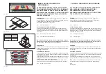
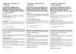
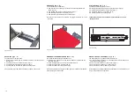
Fig.5 Abb.5

Fig.6 Abb.6

Fig.7 Abb.7

Fig.8 Abb.8

Fig.9 Abb. 9

CAP.1.

DESCRIZIONE DELLA
MACCHINA

Il sollevatore idropneumatico è fisso, cioè ancorato al suolo ed è pro-
gettato e costruito per il sollevamento e lo stazionamento in quota di
motocicli.
Il sollevatore è composto, principalmente da quattro parti:

·

"A” gruppo struttura fissa (basamento)

·

"B” gruppo mobile ( piano di sollevamento)

·

"C” gruppo di sollevamento (pompa + cilindro idraulico)

·

"D” sicurezze.

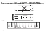
In figura 5 sono indicate le varie parti che compongono il sollevatore e
le zone di lavoro consentite e riservate al personale addetto, attorno al
sollevatore stesso.

Lato comando:

è il lato del sollevatore che comprende la zona ri-ser-

vata all’operatore in cui si accede alla pompa.

Lato posteriore

: è il lato dove è presente la lamiera fermaruota.

GRUPPO STRUTTURA FISSA (Fig.5 - A )

E’ costituito da un basamento costruito in tubi di acciaio saldati, con fori
per il fissaggio al suolo mediante tasselli ad espansione (vedere cap.4
“installazione”).

GRUPPO MOBILE (Fig.5 - B )

E’costituito da due bracci in tubi di acciaio saldati, collegati alle estremi-
tà mediante perni al basamento ed al piano di sollevamento; il quale è
dotato di una mensola estraibile per facilitare lo smontaggio della ruota
posteriore dei motocicli.

GRUPPO DI SOLLEVAMENTO (Fig.5 - C )

É costituito da:

·

Pompa idraulica a pedale ( fig.6) o Pompa pneumoidraulica (fig.7) o
Centralina elettroidraulica (fig.8)

·

un cilindro idraulico collegati fra loro mediante tubi flessibili (fig.9).

CHAP. 1

DESCRIPTION OF THE
MACHINE

The air hydraulic lift is fixed, that is anchored, to the ground and has
been designed and manufactured for lifting motorcycles and parking
them at a height.
The lift is chiefly composed of four portions:

·

"A” fixed framework unit (base);

·

"B” mobile unit (arms + lifting platform);

·

"C” lifting unit (pump + hydraulic cylinder);

·

"D” safety devices.

Figure 5 shows the various parts comprising the lift and the work areas
allowed and reserved for the assigned personnel around the lift.

Control side: the side of the lift comprising the area reserved for the
operator where the pump is accessed.

Rear side: the side where the wheel-stopping plate is fixed.

FIXED FRAMEWORK UNIT (Fig.5 - A )

It is composed of a base made of welded steel tubes, with holes for fi-
xing to the ground by means of expanding plugs (see chap. 4 “installa-
tion”).

MOBILE UNIT (Fig.5 - B )

It is composed of two arms of welded steel tubes, connected at the
ends by means of pins to the base and to the lifting platform which is
equipped with a removable bracket to help remove the rear wheel of the
motorcycle.

LIFTING UNIT (Fig. 5 - C )

It is composed of:

·

Pedal hydraulic pump (fig.6) or Air hydraulic pump (fig.7)

or Electrohydraulic unit (fig.8)

·

a hydraulic cylinder connected together by means of flexible hoses
(fig.9).

8

A

D

B

C

Содержание WML1000Q

Страница 1: ...I GB F D E SOLLEVATORE PER MOTOCICLI MOTORCYCLES LIFT EL VATEURS POUR MOTOCYCLES HEBEB HNE F R MOTORR DER ELEVADOR PARA MOTOCICLOS WML400Q WML600Q WML1000Q...

Страница 2: ......
Страница 3: ...cola N Serial N N de s rie Matrikelnummer Matr cula n Anno di costruzione Year of manufacture Ann e de fabrication Baujahr A o de fabricaci n COSTRUTTORE MANUFACTURER CONSTRUCTEUR HERSTELLER FABRICANT...

Страница 4: ...ienti e rimedi Pag 34 Appendice A Informazioniparticolari Pag 36 Appendice B Parti di ricambio Pag 36 Index Packing transport and storage Page 4 Introduction Page 6 Chap 1 Description of the machine P...

Страница 5: ...Kap 1 Maschinenbeschreibung Seite 8 Kap 2 Technische Angaben Seite 11 Kap 3 Sicherheit Seite 15 Kap 4 Installation Seite 23 Kap 5 Betriebsweise und Gebrauch Seite 27 Kap 6 Wartung Seite 30 Kap 7 St r...

Страница 6: ...mezzo delle traversine in legno come indicato in fig 4 Nei cassoni dei camion o nei containers si possono impilare fino a 4 pacchi purch vengano reggiate bene e assicurate contro la caduta Fig 4 Impi...

Страница 7: ...Hub mittels Anschlagger ten ANMERKUNG Die gew hlten Mittel m ssen f r den Hub und das Verschieben unter Sicherheitsbedingungen geeignet sein wobei Abmessungen Gewicht Schwerpunkt berstehende und empfi...

Страница 8: ...2004 108 CE 2006 42 CE 2006 95 CE NORME TECNICHE Norme Europee EN 1493 EN ISO 12100 1 2005 EN ISO 12100 2 2005 IMPIANTO ELETTRICO EN 60204 1 OPENING THE PACKING On arrival check that the machine has...

Страница 9: ...esamte Handbuch aufmerksm zu lesen bevor jeglicher Eingriff an der Hebeb hne und oder an der Verpackung ausgef hrt wird denn das Handbuch enth lt wichtige Informationen f r DIE SICHERHEIT DER PERSONEN...

Страница 10: ...C costituito da Pompa idraulica a pedale fig 6 o Pompa pneumoidraulica fig 7 o Centralina elettroidraulica fig 8 un cilindro idraulico collegati fra loro mediante tubi flessibili fig 9 CHAP 1 DESCRIPT...

Страница 11: ...e den dem Bediener vorbe haltenen Bereich ber den man Zugang zur Pumpe erh lt umfa t R ckseite Ist die Seite an der das Radsperrblech angebracht ist FESTSTEHENDE STRUKTUR Abb 5 A Die feststehende Stru...

Страница 12: ...nhalten der gehobenen He beb hne abb 10 Einem Radsperrblech an der hinteren Seite abb 11 Einem Sperrventil am Zylinder abb 12 Einem H chstdruckventil an der Pumpe Diese Sicherheitsvorrichtungen werden...

Страница 13: ...Abb 13 11 Mod Portata Capacity Kg A B C D E F G G1xG2 Kg WML 400Q 400 2000 1300 200 1030 2790 1300 350 535X700 230 WML 600Q 600 2300 1300 200 1030 2790 1300 350 535X900 265 WML 1000Q 1000 2300 1300 2...

Страница 14: ...alle dimensioni speciali del motociclo PER INGOMBRI MAGGIORI VERIFICARE IL CARICO MASSIMO E LO SBILANCIAMENTO DEL CARICO Lifting time 30 sec Lowering time 30 sec Noise level 70dB A 1m Operating temper...

Страница 15: ...nn praktisch f r das Heben aller Motorr der einge setzt werden deren Gewicht 250 600 kg berschreitet und deren Abmessungen den nachstehend aufgef hrten Abmessungen entspre chen H CHSTABMESSUNGEN DER Z...

Страница 16: ...Motor 5 Valvola di massima Max pressure valve Soupape de surpression berdruckventil V lvula de m xima 6 Valvola regolatore flusso Flow regulator valve Soupape Ventil V lvula 7 Valvola elettrica Electr...

Страница 17: ...OMPA IDRAULICA IL MANCATO RISPETTO DI QUESTE NORME PUO RECARE GRAVI DANNI ALLE PERSONE AL SOLLE VATORE ED AI MOTOCICLI SOLLEVATI CHAP 3 SAFETY It is extremely important to read this chapter carefully...

Страница 18: ...s Anhal ten von Motorr dern in gehobener Position in geschlos senen R umen entwickelt und hergestellt Jeder andere Gebrauch ist verboten Insbesondere sind diese Hebeb hnen nicht f r die Ausf hrung fol...

Страница 19: ...ano sollevati soltanto i motocicli ammessi senza superare porta ta ed ingombri previsti GENERAL PRECAUTIONS The operator and the maintenance engineer are obliged to observe the regulations contained i...

Страница 20: ...Wartungsfachmann bei auf der Hebeb hne stehendem Motorrad ausgesetzt sein k nnen und welche Schutzma nah men vom Hersteller getroffen wurden um diese Gefahren m glichst gering zu halten L NGSVERSCHIEB...

Страница 21: ...sere causato dal posizionamento non corretto del motociclo sul piano di sollevamento del sollevatore dal suo non corretto bloccaggio o da dimensioni del motociclo non compatibili con lo stesso solleva...

Страница 22: ...on berzeugt hat da sich keine Person in einer gef hrlichen Posi tion aufh lt STOSSGEFAHR Geht von den Teilen der Hebeb hne oder des Motorrads aus die sich in Personenh he befinden Wenn die Hebeb hne i...

Страница 23: ...iate vicinanze E pertanto estremamente importante attenersi scrupolosamente a tutte le regole riguardanti l uso la manutenzione e la sicurezza riportate in questo manuale IT IS FORBIDDEN TO CLIMB ONTO...

Страница 24: ...individuellen Schutzmittel rutschfeste Schuhe zu tragen GEFAHR DURCH EINE UNGEN GENDE BELEUCHTUNG Der Bediener und der Wartungsfachmann haben zu kontrollieren da alle Bereiche der Hebeb hne immer glei...

Страница 25: ...0 N mm2 Il pavimento deve inoltre essere piano e ben livellato 10 mm di tolle ranza sul livellamento Nel caso di applicazioni particolari interpellare il costruttore CHAP 4 INSTALLATION THESE OPERATIO...

Страница 26: ...he Es ist die H he der zu hebenden Motorr der unter Ber cksic htigung der max H he der Hubebene von 1030 mm zu beachten Wandabstand Mindestens 500 mm Arbeitsraum Mindestens 500 mm zuz glich zu den Ab...

Страница 27: ...ostare il sollevatore pulire i fori inserire i tasselli tipo FISCHER GM 8 o equivalenti completamente nel pavi mento quindi serrare con chiave esagonale di 13 le relative viti fig 26 ASSEMBLY ICAUTION...

Страница 28: ...rungen am Untergestellsockel anbringen Abb 24 3 Das Radsperrblech mit den Schrauben den Unterlegscheiben und den Mutterschrauben an der R ckseite der Hebeb hne befestigen Abb 25 4 Die Hebeb hne mit Dr...

Страница 29: ...gt ber folgende Steuerungen MIT PEDALPUMPE ANHEBEN DAS PUMPENPEDAL BET TIGEN ABB 28 IACHTUNG Vor dem Absenken der Hebeb hne ist sicherzustellen da sich keine Gegenst nde oder Personen unter oder in d...

Страница 30: ...Pumpe ANHEBEN DAS PUMPENPEDAL BET TIGEN ABB 30 IACHTUNG Vor dem Absenken der Hebeb hne ist sicherzustellen da sich ke ine Gegenst nde oder Personen unter oder in der N he der He beb hne befinden SENKE...

Страница 31: ...UF DEM STEUERGEH USE DR CKEN ABB 33 IACHTUNG Vor dem Absenken der Hebeb hne ist sicherzustellen da sich ke ine Gegenst nde oder Personen unter oder in der N he der He beb hne befinden SENKEN DIE MECHA...

Страница 32: ...isegni esplosi con i dati necessari per l ordinazione dei ricambi elenco dei possibili casi di malfunzionamento e delle soluzioni consi gliate cap 7 del manuale CHAP 6 MAINTENANCE ICAUTION Maintenance...

Страница 33: ...ne H ufigkeit ist als Vorschrift anzusehen und ist daher zu beachten Eine korrekte vorbeugende Wartung erfordert eine durchgehende ber wachung des Maschinenzustands Bei eventuellen St rungen wie selts...

Страница 34: ...verificare l assenza di inconvenienti ed eventuali anomalie far effettuare da parte di tecnici specializzati INTERPELLARE IL CENTRO ASSISTENZA AUTORIZZATO un controllo dell impianto idraulico pneumati...

Страница 35: ...t ist sind einige ltropfen durch den Druckluftanschluss nachzuf llen kontrollieren da die Befestigungsd bel des Untergestells festgezogen sind kontrollieren da alle Schrauben festgezogen sind kontroll...

Страница 36: ...utorizzato Inconveniente di fun zionamento della pompa WML Chiamare il centro di assistenza autorizzato Presenza di trafila menti dallo stelo del cilindro Impurit e o sporcizia all interno del cilindr...

Страница 37: ...Nicht genug l im Beh lter Ungen gender Spei sedruck des Kreises M gliche Verschmut zung der Ventile Das Ablassventil ist nicht geeicht Den autorisierten Kun dendienst in Anspruch nehmen St rung UPF D...

Страница 38: ...indicare il codice del pezzo richiesto vedere nelle tabelle le co lonne CODICE indicare la quantit richiesta La richiesta deve essere fatta al rivenditore autorizzato indicato nel frontespi APPENDIX A...

Страница 39: ...SATZTEILE Beim Auswechseln der Ersatzteile und bei eventuellen Reparaturen sind ALLE VORSICHTSMASSNAHMEN zu treffen die in Kapitel 6 WARTUNG und in Kapitel 3 SICHERHEIT enthalten sind Es sind alle Ma...

Страница 40: ...i erkl rer hermed at autol fter model hereby we declare that the lift model Vi f rklarer h rmed att billyft model hiermit erkl ren wir da die Hebeb hne Type verklaren hiermee dat WML400Q Matricola N N...

Страница 41: ...od le Vi erkl rer hermed at autol fter model hereby we declare that the lift model Vi f rklarer h rmed att billyft model hiermit erkl ren wir da die Hebeb hne Type verklaren hiermee dat WML600Q Matric...

Страница 42: ...od le Vi erkl rer hermed at autol fter model hereby we declare that the lift model Vi f rklarer h rmed att billyft model hiermit erkl ren wir da die Hebeb hne Type verklaren hiermee dat WML1000Q Matri...

Отзывы: