


REV. 01 2013
13 / 24
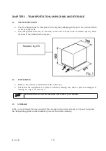
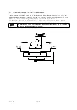
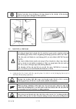
4.3 COMMISSIONING
Any electric connection job must be carried out by professionally qualified
personnel.
Make sure that the power supply is right.
Make sure the connection of the phases is right. Improper electrical hook-up
can damage motor and will not be covered under warranty.
x
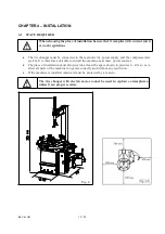
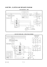
Check to make sure the characteristics of your systems correspond to those required by the
machine. If you have to change the machine’s operating voltage, make the necessary
adjustments to the terminal board referring to the electric diagram in
chapter 9.
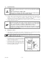
x
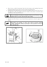
Connect the machine to the compressed air system by means of the air connection (Q) that
protrudes from the rear section
.
Connect the machine to the electric network, which must be provided with line
fuses, a good earth plate in compliance with regulations in force and it must be
connected to an automatic circuit breaker (differential) set at 30 mA.
Should the tire-changer be lacking in electric plug, the user must set one, which
is at least 16 A and which conforms to the voltage of the machine, in compliance
with the regulations in force.
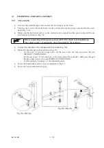
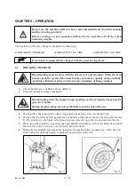
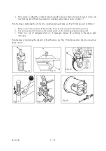
4.4 OPERATING TESTS
x
When pedal (Z) is pressed down the turntable (Y) should turn in a clockwise direction. When
pedal is pulled up the turntable should turn in an anticlockwise direction.
If the turntable turns in the opposite direction to that shown, reverse two of the
wires in the tree-phase plug.
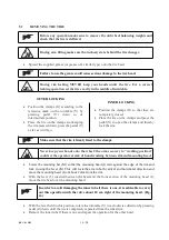
x
Pressing the pedal (U) activates the bead breaker
(R); when the pedal is released the bead breaker
returns to its original position.
x
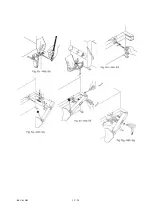
Pressing the pedal (V) opens the four clamps
(G); when the pedal is pressed again they close.
x
Pressing the trigger on the airline gauge cause
air to be released from the head.
Fig. 6
Содержание TITANIUM BIKE
Страница 2: ......
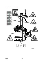
Страница 9: ...REV 01 2013 7 24 2 3 DANGER WARNING SIGNS Fig 2 ...
Страница 14: ...REV 01 2013 12 24 ...
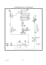
Страница 26: ...REV 01 2013 24 24 STANDARD PNEUMATIC SYSTEM DIAGRAM ...
Страница 27: ......
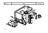
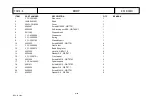
Страница 28: ... 2 22 REV 01 2013 BODY TAV 1 1 ED 04 13 ...
Страница 30: ... 4 22 REV 01 2013 HORIZ AND VERT ARMS TAV 2 1 ED 04 13 ...
Страница 33: ... 7 22 REV 01 2013 PEDAL BOX TAV 3 1 ED 04 13 ...
Страница 37: ... 11 22 REV 01 2013 BEAD BREAKER TAV 4 1 ED 04 13 ...
Страница 40: ... 14 22 REV 01 2013 SELFͲCENTERING TURNTABLE TAV 5 1 ED 04 13 ...
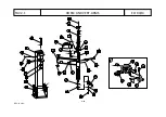
Страница 44: ... 18 22 REV 01 2013 3 MOTOR REDUCTION GEAR GROUP TAV 6 0 ED 04 13 ...
Страница 47: ... 21 22 REV 01 2013 AIR LUBRICATOR GROUP TAV 8 1 ED 04 13 ...


