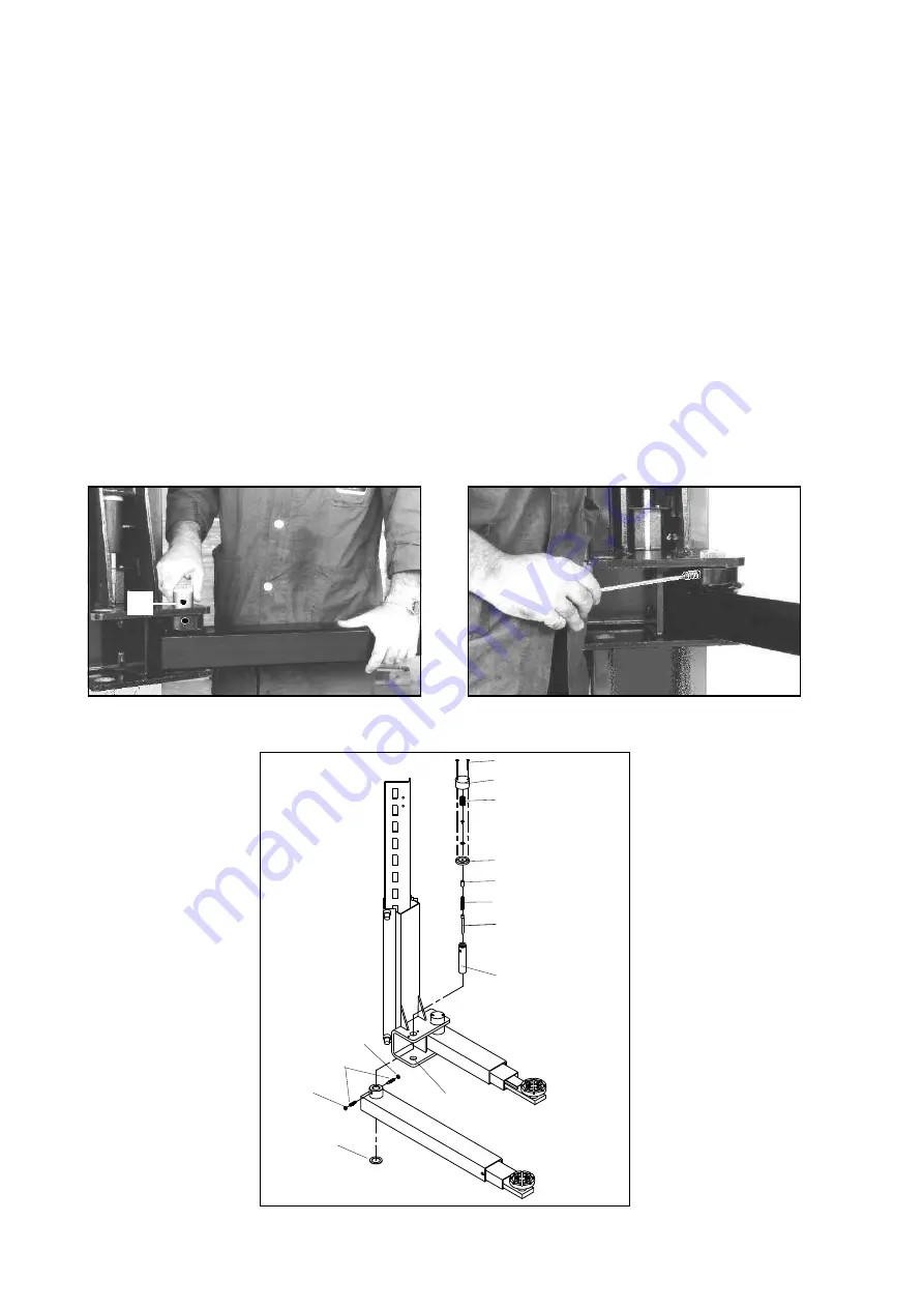
MONTAGGIO BRACCI E DISPOSITIVI DI BLOCCAGGIO-(Fig.49)
1 - Premendo il pulsante di salita, portare la parte inferiore dei
carrelli ad un’ altezza di circa 70 cm da terra, quindi premere il
pulsante di stazionamento.
PORTARE L’ INTERRUTTORE GENERALE (QS) IN POSIZIONE
“O” E TOGLIERE L’ ALIMENTAZIONE AL SOLLEVATORE.
I
ATTENZIONE
La spina dentata (10) e la rondella dentata (5) devono essere
accoppiati e non appoggiati uno sull’altro. Fare attenzione a
non danneggiare i denti durante l’accoppiamento. Non utiliz-
zare martelli per effettuare l’accoppiamento!
2 - Ingrassare i fori diametro 40 alle estremità dei bracci.
3 - Montare i bracci sul supporto (2) nella parte inferiore del carrel-
lo con la rondella in nylon (12 Fig. 49) inserita sotto al braccio,
introdurre le spine dentate (1) nel supporto attraverso gli attacchi
sul braccio (Vedere Fig.47).
Ad operazione ultimata occorre che i 2 fori ciechi D=10,5 sulla spi-
na (con funzione di sede per l’ estremità del grano M14) siano in
corrispondenza dei fori M14 sul supporto del carrello (Fig.47).
4 - Inserire i grani M14 (3) avvitando i relativi controdadi (4) dall’ in-
terno del supporto tubolare, serrarli contro il perno e bloccare con i
controdadi (Fig.48).
Fig.47
5 - Inserire il perno spingimolla
(5) nella spina dentata (1) e
successivamente la molla (6),
avendo cura di ingrassare le
suddette parti prima di montar-
le.
6 - Inserire lo spinotto (7) com-
pleto di rondella dentata (8)
(preassemblati dal costruttore)
sull’ estremità scanalata della
spina che sporgerà dal braccio
di alcuni millimetri.
Montare quindi la molla (9) fa-
cendone coincidere il diametro
interno con la rondella posta
sulla rondella dentata.
Coprire con il cappellotto (10),
inserire le viti (11), centrando i
fori sui bracci, quindi serrarle.
ARM ASSEMBLING (Fig.49)
1 - Press the up push button, raise the carriages to a height of
about 70 cm off the ground, then press the park push button,
SET THE MAIN SWITCH (QS) TO POSITION 0 AND CUT OFF
THE POWER SUPPLY TO THE LIFT.
I
WARNING
The dowel pin (10) and locking washer (5) are matched pairs
do not mix them up. Be very careful not to demage the spline
teeth when fitting. Do not use a hammer!
2 - Grease the holes ø 40 on the arms ends.
3 - Mount the arms into the carriage supports with the nylon wa-
sher (12 Fig. 49) fitted under the arm, insert the dowel pins into the
support holes as shown in fig.47.
After completing the operation, the attachment hole of the pins (the
place to put the headless screw M14) on the arm must coincide
with M14 drills on the carriage support (fig.47).
4 - Insert the M14 headless screws screwing the relative counter-
nuts from the inside of the carriage support, tighten them against
the pin and block them with counternuts (Fig.48).
Fig.48
5 - (Fig.52) Insert the spring
thrusting pin (5) into the dowel
pin (1) and then the spring (6),
making sure to grease the afo-
rementioned parts before mo-
unting them.
6 - Insert the pin (7) complete
with lock washer (8) (pre-as-
sembled by the manufacturer)
on the grooved end of the pin
that will project from the arm
support by a few millimetres.
Then mount the spring (9) ma-
king the internal diameter coin-
cide with the washer located on
the lock washer (5).
Cover with the cap (10), insert
the screws (11), centering the
holes of the arm support, and
then tighten the screws.
29
Fig.49
6
5
3
2
1
4
4
7
8
5
9
10
11
1
4
12
Содержание 232I
Страница 1: ...I SOLLEVATORE ELETTROIDRAULICO A 2 COLONNE GB 2 POST ELECTRO HYDRAULIC LIFT 232I ...
Страница 2: ......
Страница 40: ...CARRELLI E BRACCI CARRIAGES AND ARMS SCHLITTEN UND ARME CHARIOTS ET BRAS CARROS Y BRAZOS ...
Страница 41: ...SICUREZZE SAFETY DEVICES SICHERHEITSVORRICHTUNGEN DISPOSITIFS DE SÉCURITÉ DISPOSITIVOS DE SEGURIDAD ...


