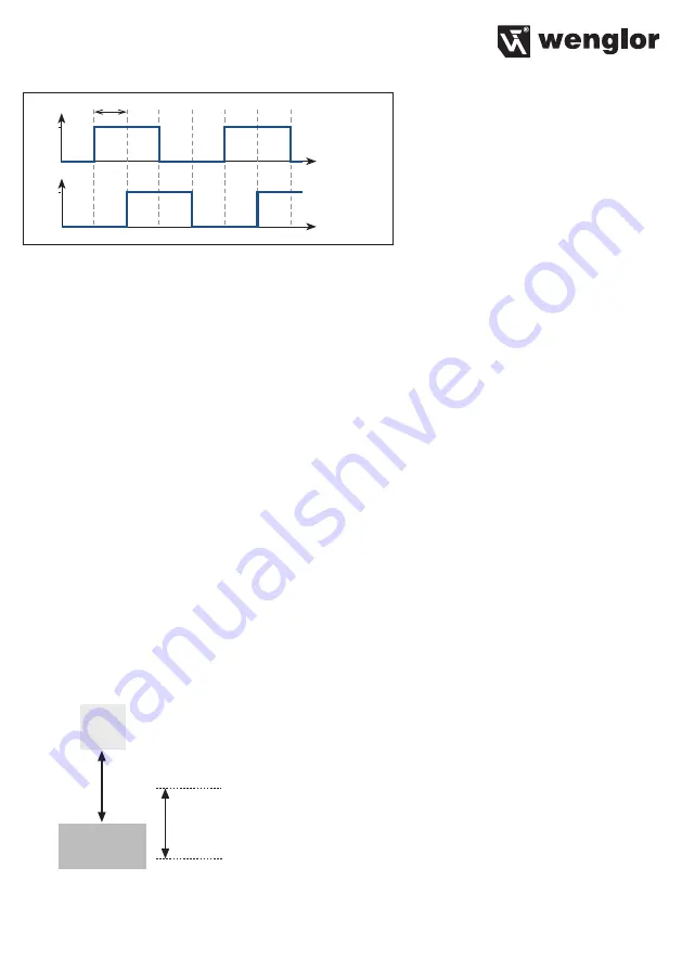
25
90°
E1/A
E2/B
5...24 V
0 V
0 V
5...24 V
Displacement
Displacement
• Encoder E1+E2: A 2-channel rotary encoder with HTL square-wave signal must be used. Channel A is
displaced 90° relative to channel B. It must be assured that a shielded cable is used in order to avoid pos-
sible interference or crosstalk between the conductors.
• Encoder reset: The encoder is reset to “0”.
• Laser off: The laser can be switched on or off by activating the input load or the input voltage.
Output:
• PNP output: The load or the analysis module is connected between the minus pole (reference) and the
output. When switched, the output is connected to the plus pole via an electronic switch. A PNP output
can also be equipped with a pull-down resistor.
• NPN output: The load or the analysis module is connected between the plus pole (reference) and the out-
put. When the sensor is switched, the output is connected to the minus pole via an electronic switch. An
NPN output can also be equipped with a pull-up resistor.
• Push-pull: alternate PNP and NPN switching
Output function:
• The output can be configured as NO (normally open) or NC (normally closed).
Teach-in mode:
• Teach-in: a function by means of which the sensor is caused to automatically calculate and save future set-
tings based upon momentarily acquired values by pressing a button or applying a control signal.
• FT teach-in mode (window teach-in): There are two switching points in the case of window teach-in. The dis-
tance between the two switching points is called the window. The size of the window is designated window
width. The sensor is switched when an object is within the window.
Sensor
Object
Switching Point 1
Switching Point 2
Window Width
Teach-in distance
• VT teach-in mode (foreground teach-in): Teach-in is performed while the sensor is aligned to the object.


