MAINTENANCE
WARNING!
Always turn the planer OFF and disconnect it from the power source before starting any main-
tenance work.
ADJUSTING/REPLACING CUTTING INSERTS
The cutterhead is equipped with 26 indexable cutting inserts. Each insert can be rotated 90 degrees to expose a
fresh edge; if one edge becomes dull, the other may be used.
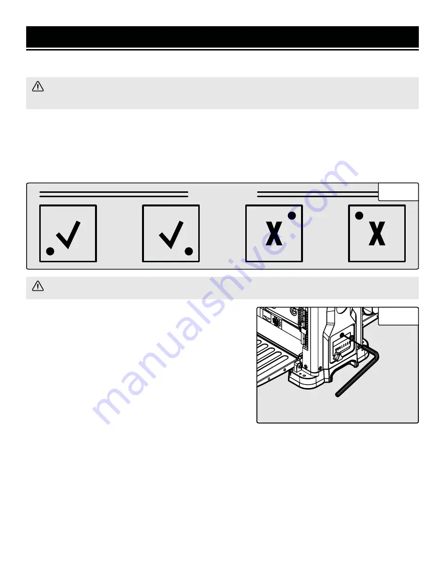
Additionally, each insert has a reference dot on one corner. As the insert is rotated, the dot location can be used as
an indicator of which edges are used, and which are new. When each cutting insert has been rotated once, it is time
to replace the cutting insert.
WARNING!
NEVER grasp the cutterhead with unprotected hands. This will result in serious injury.
To rotate or replace cutting inserts:
1. Put on cutproof gloves. A magnet or pair of needle-nose pli-
ers may also be needed.
2. Adjust the rollercase to a height of about 2-1/4” (refer to the
depth scale, Fig. 7 - 2). Remove the dust chute.
3. Insert the included hex wrench into the hole above the depth
stop label (Fig. 11; adjust the height of the rollercase if neces-
sary). Use the hex wrench to turn the cutterhead, so the cutting
inserts in question are easily accessible. Hold the hex wrench
steady to hold the cutterhead in place.
16
CUTTERHEAD
4. Use the star wrench to loosen the mounting screws. Remove the cutting inserts.
NOTE:
You may want take a picture of the cutterhead before removing the inserts, so they can be re-installed in the
correct orientation.
5. Clean off any dust or debris from the inserts, as well as the cutterhead. Rotate or replace the insert so a fresh edge
faces outward (Figs. 10). Make sure the side of the cutting insert is flush against the cutterhead ridge.
6. Re-install the screws and tighten.
NOTE:
Proper cleaning of the inserts and cutterhead is crucial to achieving a good-quality cut. Dirt or dust trapped
between the insert and cutterhead will cause the insert to be improperly mounted, and may create noticeable marks
on the workpiece.
Fig. 11
Fig. 10


