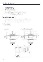
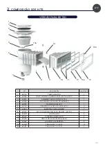
background image

71


Usando um X-Acto/faca, corte 

o revestimento para revelar a 

abertura do skimmer. Remover a 

parte cortada do revestimento.


Encaixe a proteção dos parafusos 

na flange.

PT

Содержание SKIMMER A500 NHL

Страница 1: ...R ENG DE ES IT NL PT FR ENG DE ES IT NL PT p 2 p 12 p 22 p 32 p 42 p 52 p 62 GUIDE D INSTALLATION INSTALLATION MANUAL INSTALLATIONSANLEITUNG GUÍA DE INSTALACIÓN GUIDA ALL INSTALLAZIONE INSTALLATIEHANDLEIDING MANUAL DE INSTALAÇÃO ...

Страница 2: ...e Volet flottant silencieux Trop plein Ø50mm extérieur Sorties Ø50mm intérieur x2 1 1 2 intérieur ou 2 extérieur RÉCEPTION DU MATÉRIEL 1 colis contenant la meurtrière complète accessoires 1 colis contenant le boitier complet accessoires DIMENSIONS béton béton liner panneau liner ...

Страница 3: ...1 5 60284 OBTURATEUR DE FOND SKIMMER 1 7 60392 BOITIER MONOBLOC 1 8 64130 PINCES MEURTRIÈRE 4 9 62341 BARRIÈRE POUR SKIMMER 1 10 80470 MEURTRIÈRE A500 DESIGN BÉTON 1 11 80493 JOINT A500 2 12 80491 CONTRE BRIDE A500 1 13 80492 CACHE VIS A500 1 14 62461 ARRÊT BARRIÈRE 2 15a 60469 VIS TF 5 5X25 13 15b 62423 VIS TF 3 9X25 9 1 2 3 4 5 6 7 8 9 10 11 12 15a 15a 15b 13 14 FR ...

Страница 4: ...0 PINCES MEURTRIÈRE 4 9 62341 BARRIÈRE POUR SKIMMER 1 10 80493 JOINT A500 2 11 80491 CONTRE BRIDE A500 1 12 80492 CACHE VIS A500 1 13 62461 ARRÊT BARRIÈRE 2 14 80490 MEURTRIÈRE A500 DESIGN PANNEAU 1 15a 62419 RONDELLE INOX M5 11 15b 62420 ECROU INOX M5 11 15c 62418 VIS TF M5X20 11 15d 60469 VIS TF 5 5X25 13 15e 62423 VIS TF 3 9X25 9 1 2 3 4 5 6 7 8 9 15a 15b 15c 15d 15d 15e 10 11 12 14 13 2 compos...

Страница 5: ...ur la surface indiquée sur les deux parties du Skimmer grâce au tube de colle fournie ATTENTION Unefoislesdeuxpartiescollées ilestpratiquement impossible de les séparer au bout d une 1 2 heure Pour faciliter le maintien des parties du Skimmer glisser les quatre pinces à la jonction du Skimmer S assurer du contact sur tout le contour de la jonction FR ...

Страница 6: ...lage autour du Skimmer à noter que les nervures supérieures de la meurtrière A500 peuvent accueillir des fers à béton de Ø12mm max 1 Re contrôler le niveau du boitier puis couler le béton à l arase du cache vis2 nous préconisons 30mm de béton minimum au dessus du boitier Assembler la bride et le cache vis sur la meurtrière du Skimmer 1 1 2 2 ...

Страница 7: ...s nervures supérieures de la meurtrière A500 peuvent accueillir des fers à béton de Ø12mm max 1 Re contrôler le niveau du boitier puis couler le béton à l arase de la meurtrière2 nous préconisons 30mm de béton minimum au dessus du boitier Poser le premier joint plat côté adhésif sur la surface de la meurtrière Procéder ensuite à la pose du liner si présent 2 2 1 1 FR ...

Страница 8: ...ache vis sur la bride Placer le second joint côté plat adhésif sur la bride Positionner ensuite la bride sur le liner en alignant les axes des trous avec la meurtrières puis visser l ensemble des vis Il est préférable de finir le serrage de ces dernières avec un tournevis plutôt qu une visseuse pour éviter d abîmer la pièce ...

Страница 9: ...er 155mm minimum x540mm Positionner le Skimmer dans l ouverture puis percer Ø5 5mm l ensemble des trous pour les boulons Penser à contrôler le niveau du boitier Visser les boulons pour maintenir la position du Skimmer sur la structure VERSION PANNEAU LINER 540 155 minimum FR ...

Страница 10: ...le liner en alignant les axes des trous avec la meurtrières puis visser l ensemble des vis Poser le premier joint plat côté adhésif sur la surface de la meurtrière Mettre en place le ferraillage autour du Skimmer à noter que les nervures supérieures de la meurtrière A500 peuvent accueillir des fers à béton de Ø12mm max ...

Страница 11: ...11 A l aide d un cutter découper le liner de façon à découvrir l ouverture du Skimmer Enlever la chute de liner Clipser le cache vis sur la bride FR ...

Страница 12: ...floating shutter Overflow Ø 50 mm OD Outlets Ø 50 mm ID x 2 1 internal thread or 2 external thread RECEIPT OF THE EQUIPMENT One package containing the complete mouth accessories One packaging containing the complete control unit accessories WATER LINE concrete panel liner ...

Страница 13: ...ER BOTTOM SHUTTER 1 7 60392 ONE PIECE CONTROL UNIT 1 8 64130 MOUTH CLAMP 4 9 62341 SKIMMER BARRIER 1 10 80470 A500 DESIGN MOUTH CONCRETE 1 11 80493 A500 GASKET 2 12 80491 A500 COUNTER FLANGE 1 13 80492 A500 SCREW COVER 1 14 62461 BARRIER STOP 2 15a 60469 5 5 X 25 MM FLAT HEAD SCREW 13 15b 62423 3 9 X 25 MM FLAT HEAD SCREW 9 1 2 3 4 5 6 7 8 9 10 11 12 15a 15a 15b 13 14 ENG ...

Страница 14: ... 62341 SKIMMER BARRIER 1 10 80493 A500 GASKET 2 11 80491 COUNTER FLANGE A500 1 12 80492 A500 SCREW COVER 1 13 62461 BARRIER STOP 2 14 80490 A500 DESIGN MOUTH PANEL 1 15a 62419 M5 STAINLESS STEEL WASHER 11 15b 62420 M5 STAINLESS STEEL NUT 11 15c 62418 M5 20 MM FLAT HEAD SCREW 11 15d 60469 5 5 X 25 MM FLAT HEAD SCREW 13 15e 62423 3 9 X 25 MM FLAT HEAD SCREW 9 1 2 3 4 5 6 7 8 9 15a 15b 15c 15d 15d 15...

Страница 15: ...rovided in the kit to the area shown here on both sections of the Skimmer WARNING Once the two sections have been glued together it will be nearly impossible to separate them after hour has passed To hold the sections of the Skimmer in place while the glue is drying at tach the four clamps at the point of junction Ensure contact is made all the way around the junction ENG ...

Страница 16: ...round the Skimmer note that the top ribs of the A500 mouth can accommodate rebar of Ø 12 mm maximum 1 Re check the level of the control unit and then pour the concrete at the edge of the screw cover 2 we recommend at least 30 mm of concrete over the control unit Assemble the flange and the screw cover on the mouth of the Skimmer 1 1 2 2 ...

Страница 17: ...t the top ribs of the A500 mouth can accommodate rebar of Ø 12 mm maximum 1 Re check the level of the control unit and then pour the concrete at the edge of the mouth 2 we recommend at least 30 mm of concrete over the control unit Affix the first flat gasket with the adhesive side against the surface of the mouth Then install the liner if present 2 2 1 1 ENG ...

Страница 18: ...he screw cover to the flange Affix the second gasket with the adhesive side against the flange Then position the flange on the liner by lining up the holes with the mouth and then screw in all of the screws It is better to finish tightening these with a screwdriver rather than a screwdriver to avoid damaging the room ...

Страница 19: ... 155 mm minimum x 540 mm Position the Skimmer in the opening and then drill all of the holes Ø 5 5 mm for the bolts Remember to check the level of the control unit Screw in the bolts to hold the Skimmer in place on the structure PANEL LINER KIT 540 155 minimum ENG ...

Страница 20: ...e flange on the liner by lining up the holes with the mouth and then screw in all of the screws Affix the first flat gasket with the adhesive side against the surface of the mouth Set up the reinforcement around the Skimmer note that the top ribs of the A500 mouth can accommodate rebar of Ø 12 mm maximum ...

Страница 21: ...21 Use a box cutter to clear a hole the liner so as to uncover the Skimmer s opening Remove the liner offcuts Clip the screw cover to the flange ENG ...

Страница 22: ... Überlauf 50 mm Außendurchmesser Ausgänge 50 mm Innendurchmesser x2 1 5 Zoll innen oder 2 Zoll außen EMPFANG DES MATERIALS Ein Paket mit der kompletten Saugöffnung und ihrem Zubehör Ein Paket mit der kompletten Steuereinheit und ihrem Zubehör WASSERLINIE betonschwimmbecken platten schwimmbecken mit folienauskleidung ...

Страница 23: ...ILTER 1 5 60284 STOPFEN DES SKIMMERBODENS 1 7 60392 MONOBLOCKGEHÄUSE 1 8 64130 KLEMME SAUGÖFFNUNG 4 9 62341 SKIMMERKLAPPE 1 10 80470 SAUGÖFFNUNG A500 DESIGN BETON 1 11 80493 DICHTUNG A500 2 12 80491 GEGENFLANSCH A500 1 13 80492 ABDECKBLENDE A500 1 14 62461 KLAPPENANSCHLAG 2 15a 60469 SCHRAUBE TF 5 5X25 13 15b 62423 SCHRAUBE TF 3 9X25 9 1 2 3 4 5 6 7 8 9 10 11 12 15a 15a 15b 13 14 DE ...

Страница 24: ... 64130 KLEMME SAUGÖFFNUNG 4 9 62341 SKIMMERKLAPPE 1 10 80493 DICHTUNG A500 2 11 80491 GEGENFLANSCH A500 1 12 80492 ABDECKBLENDE A500 1 13 62461 KLAPPENANSCHLAG 2 14 80490 SAUGÖFFNUNG A500 DESIGN PLATTE 1 15a 62419 EDELSTAHL BEILAGSCHEIBE M5 11 15b 62420 EDELSTAHL MUTTER M5 11 15c 62418 SCHRAUBE TF M5X20 11 15d 60469 SCHRAUBE TF 5 5X25 13 15e 62423 SCHRAUBE TF 3 9X25 9 1 2 3 4 5 6 7 8 9 15a 15b 15c...

Страница 25: ...s mithilfe der mitgelieferten Tube einen Strang Klebstoff auf ACHTUNG Wenn die beiden Teile zusammengeklebt sind ist es nach Ablauf einer halben Stunde beinahe unmöglich sie wieder zu trennen Damit die Skimmerteile gut zusammengepresst bleiben schieben Sie die vier Klemmen auf die Nahtstelle des Skimmers Prüfen Sie ob die beiden Teile über die gesamte Nahtstelle gut zusammengedrückt werden DE ...

Страница 26: ...er an die oberen Rippen der Saugöffnung A500 können Betoneisen von max Ø12mm aufnehmen 1 Prüfen Sie die waagrechte Ausrichtung des Gehäuses erneut und gießen Sie mit Beton bündig bis zur Abdeckblende aus2 wir empfehlen eine Betonschicht von mindestens 30 mm über dem Gehäuse Befestigen Sie den Flansch und die Abdeckblende auf der Saugöffnung des Skimmers 1 1 2 2 ...

Страница 27: ...öffnung A500 können Betoneisen von max Ø12mm aufnehmen 1 Prüfen Sie die waagrechte Ausrichtung des Gehäuses erneut und gießen Sie mit Beton bündig bis zur Saugöffnung aus2 wir empfehlen eine Betonschicht von mindestens 30 mm über dem Gehäuse Setzen Sie die erste Flachdichtung auf die Saugöffnung sodass die Klebeseite zur Saugöffnung zeigt Positionieren Sie anschließend die Folie falls vorhanden 2 ...

Страница 28: ...tionieren Sie die zweite Flachdichtung mit der Klebeseite auf den Flansch Positionieren Sie anschließend den Flansch auf die Folie wobei Sie auf die korrekte Ausrichtung der Achsen der Löcher mit der Saugöffnung achten Ziehen Sie anschließend alle Schrauben fest Es ist besser diese mit einem Schraubendreher als mit einem Schraubendreher festzuziehen um eine Beschädigung des Teils zu vermeiden ...

Страница 29: ... mm Positionieren Sie den Skimmer im Ausschnitt und bohren Sie alle Löcher Ø 5 5 mm für die Schrauben Denken Sie daran die richtige Ausrichtung des Gehäuses zu prüfen Ziehen Sie die Schrauben fest um die Position des Skimmers auf der Struktur zu halten PLATTEN SCHWIMMBECKEN MIT FOLIENAUSKLEIDUNG 540 155 minimum DE ...

Страница 30: ...e wobei Sie auf die korrekte Ausrichtung der Achsen der Löcher mit der Saugöffnung achten Ziehen Sie anschließend alle Schrauben fest Setzen Sie die erste Flachdichtung auf die Saugöffnung sodass die Klebeseite zur Saugöffnung zeigt Bringen Sie die Armierung rund um den Skimmer an die oberen Rippen der Saugöffnung A500 können Betoneisen von max Ø12mm aufnehmen ...

Страница 31: ...31 Schneiden Sie mithilfe eines Cutters die Folie aus sodass die Öffnung des Skimmers frei liegt Entfernen Sie die ausgeschnittene Folie Bringen Sie die die Abdeckblende auf dem Flansch an DE ...

Страница 32: ... ajuste Compuerta flotante silenciosa Rebosadero Ø 50 mm exterior Salidas Ø 50 mm interior x 2 1 1 2 interior o 2 exterior RECEPCIÓN DEL EQUIPO Un paquete con la tronera completa sus accesorios Un paquete con el cuerpo completo sus accesorios LÍNEA DE AGUA hormigón panel líner ...

Страница 33: ...URADOR DE FONDO SKIMMER 1 7 60392 CUERPO MONOBLOQUE 1 8 64130 PINZAS TRONERA 4 9 62341 PORTEZUELA PARA SKIMMER 1 10 80470 TRONERA A500 DESIGN HORMIGÓN 1 11 80493 JUNTA A500 2 12 80491 CONTRABRIDA A500 1 13 80492 EMBELLECEDOR A500 1 14 62461 TOPE DE PORTEZUELA 2 15a 60469 TORNILLO TF 5 5 X 25 13 15b 62423 TORNILLO TF 3 9 X 25 9 1 2 3 4 5 6 7 8 9 10 11 12 15a 15a 15b 13 14 ES ...

Страница 34: ...1 PORTEZUELA PARA SKIMMER 1 10 80493 JUNTA A500 2 11 80491 CONTRABRIDA A500 1 12 80492 EMBELLECEDOR A500 1 13 62461 TOPE DE PORTEZUELA 2 14 80490 TRONERA A500 DESIGN PANEL 1 15a 62419 ARANDELA ACERO INOXIDABLE M5 11 15b 62420 TUERCA ACERO INOXIDABLE M5 11 15c 62418 TORNILLO TF M5 X 20 11 15d 60469 TORNILLO TF 5 5 X 25 13 15e 62423 TORNILLO TF 3 9 X 25 9 1 2 3 4 5 6 7 8 9 15a 15b 15c 15d 15d 15e 10...

Страница 35: ...ficie indicada en am bas piezas del skimmer con el tubo de adhesivo suministrado ATENCIÓN Una vez pegadas ambas piezas será casi imposible separarlas al cabo de una media hora Para simplificar el mantenimiento de las piezas del skimmer deslice las cuatro pinzas hasta la unión del skimmer Asegúrese de que esté en contacto todo el contorno de la unión ES ...

Страница 36: ... observe que los nervios superiores de la tronera A500 pueden albergar varillas para hormigón de Ø 12 mm como máximo1 Vuelva a comprobar la nivelación del cuerpo y luego vierta el hormigón al ras del embellecedor2 recomendamos al menos 30 mm de hormigón por encima del cuerpo Monte la brida y el embellecedor de los tornillos en la tronera del skimmer 1 1 2 2 ...

Страница 37: ... de la tronera A500 pueden albergar varillas para hormigón de Ø 12 mm como máximo1 Vuelva a comprobar la nivelación del cuerpo y luego vierta el hormigón al ras de la tronera2 recomendamos al menos 30 mm de hormigón por encima del cuerpo Coloque la primera junta plana con la cara adhesiva hacia la superficie de la tronera A continuación proceda a colocar el líner si existe 2 2 1 1 ES ...

Страница 38: ...llecedor a la brida Coloque la segunda junta plana con la cara adhesiva hacia la brida A continuación coloque la brida en el líner alineando los ejes de los orificios con la tronera y luego sujete el conjunto con los tornillos Es mejor terminar de apretarlos con un destornillador en lugar de un destornillador para evitar dañar la pieza ...

Страница 39: ...imo x 540 mm Coloque el skimmer en la abertura y luego taladre Ø 5 5 mm todos los orificios para los pernos No olvide controlar la nivelación del cuerpo Enrosque las tuercas a los pernos para mantener el skimmer en posición en la estructura VERSION PANNEAU LINER 540 155 minimum ES ...

Страница 40: ... alineando los ejes de los orificios con la tronera y luego sujete el conjunto con los tornillos Coloque la primera junta plana con la cara adhesiva hacia la superficie de la tronera Instale las varillas alrededor del skimmer observe que los nervios superiores de la tronera A500 pueden albergar varillas para hormigón de Ø 12 mm como máximo ...

Страница 41: ...41 Con un cúter recorte el líner de manera que la abertura del skimmer quede al descubierto Retire el recorte de líner Enganche el embellecedor a la brida ES ...

Страница 42: ...Copertura a tapparella silenziosa Trabocco Ø50 mm esterno Uscite Ø50 mm interno x2 1 1 2 interno o 2 esterno RICEZIONE DEL MATERIALE Un pacco contenente la bocchetta completa e gli accessori Un pacco contenente la scatola completa e gli accessori LINEA DELL ACQUA cemento pannello rivestimento ...

Страница 43: ...ORE DI FONDO SKIMMER 1 7 60392 ALLOGGIO MONOBLOCCO 1 8 64130 MORSETTI BOCCHETTA 4 9 62341 BATTENTE PER SKIMMER 1 10 80470 BOCCHETTA A500 DESIGN CEMENTO 1 11 80493 GUARNIZIONE A500 2 12 80491 CONTROFLANGIA A500 1 13 80492 NASCONDI VITE A500 1 14 62461 FERMO BATTENTE 2 15a 60469 VITE TF 5 5X25 13 15b 62423 VITE TF 3 9X25 9 1 2 3 4 5 6 7 8 9 10 11 12 15a 15a 15b 13 14 IT ...

Страница 44: ... MORSETTI BOCCHETTA 4 9 62341 BATTENTE PER SKIMMER 1 10 80493 GUARNIZIONE A500 2 11 80491 CONTROFLANGIA 1 12 80492 NASCONDI VITE A500 1 13 62461 FERMO BATTENTE 2 14 80490 BOCCHETTA A500 DESIGN PANNELLO 1 15a 62419 RONDELLA INOX M5 11 15b 62420 DADO INOX M5 11 15c 62418 VITE TF M5X20 11 15d 60469 VITE TF 5 5X25 13 15e 62423 VITE TF 3 9X25 9 1 2 3 4 5 6 7 8 9 15a 15b 15c 15d 15d 15e 10 11 12 14 13 2...

Страница 45: ...colla continuo sulla superficie indicata su entrambe le parti dello skimmer ATTENZIONE Una volta che le due componenti sono state incollate è praticamente impossibile staccarle dopo 1 2 ore Per semplificare la tenuta delle componenti dello skimmer inserire i quattro morsetti nella giunzione dello skimmer Accertarsi che la giun zione tocchi l intero perimetro IT ...

Страница 46: ...turaattorno allo skimmer da notare che il reticolato superiore della bocchetta A500 è in grado di ospitare tondini per il cemento da Ø12 mm max 1 Riverificare il livello della scatola e poi colare il cemento alla base del nascondi vite2 suggeriamo min 30 mm di cemento sopra la scatola Montare la flangia e il nascondi vite sulla bocchetta dello skimmer 1 1 2 2 ...

Страница 47: ...e il reticolato superiore della bocchetta A500 è in grado di ospitare tondini per il cemento da Ø12 mm max 1 Riverificare il livello della scatola e poi colare il cemento alla base della bocchetta2 suggeriamo min 30 mm di cemento sopra la scatola Posizionare la prima guarnizione piatta adesiva sul perimetro della bocchetta Procedere quindi al posizionamento del rivestimento se presente 2 2 1 1 IT ...

Страница 48: ...liato Fissare il nascondi vite sulla flangia Posizionare la seconda guarnizione piatta adesiva sulla flangia Posizionare quindi la flangia sul rivestimento allineando gli assi dei fori con la bocchetta quindi avvitare tutte le viti È meglio finire di serrarli con un cacciavite piuttosto che con un cacciavite per evitare di danneggiare la parte ...

Страница 49: ...inimo x 540 mm Posizionare lo skimmer nell apertura e poi forare Ø5 5 mm l insieme dei fori per i bulloni Ricordarsi di verificare il livello della scatola Avvitare i bulloni per mantenere stabile la posizione dello skimmer sulla struttura VERSIONE PANNELLO RIVESTIMENTO 540 155 minimum IT ...

Страница 50: ...ngia sul rivestimento allineando gli assi dei fori con la bocchetta quindi avvitare tutte le viti Posizionare la prima guarnizione piatta adesiva sul perimetro della bocchetta Posizionare l armatura attorno allo skimmer da notare che il reticolato superiore della bocchetta A500 è in grado di ospitare tondini per il cemento da Ø12 mm max ...

Страница 51: ...51 Aiutandosi con un taglierino ritagliare il rivestimento in modo da scoprire l apertura dello skimmer Rimuovere la parte di rivestimento ritagliato Fissare il nascondi vite sulla flangia IT ...

Страница 52: ...egelafsluiter Geruisloos vlottend luik Overloop buiten Ø50mm Uitgangen Binnen Ø50mm x2 1 1 2 binnen of 2 buiten ONTVANGST VAN HET MATERIAAL 1 collo met de volledige meurtrière toebehoren 1 collo met het volledige kastje toebehoren WATERLIJN betonnen paneel voering ...

Страница 53: ...60284 BODEMAFSLUITER SKIMMER 1 7 60392 MONOBLOC KASTJE 1 8 64130 MEURTRIÈRE KLEMMEN 4 9 62341 HEK VOOR SKIMMER 1 10 80470 MEURTRIÈRE A500 DESIGN BETON 1 11 80493 DICHTING A500 2 12 80491 CONTRAFLENSA500 1 13 80492 SCHROEFAFDEKKING A500 1 14 62461 STOP HEK 2 15a 60469 SCHROEVEN TF 5 5X25 13 15b 62423 SCHROEVEN TF 3 9X25 9 1 2 3 4 5 6 7 8 9 10 11 12 15a 15a 15b 13 14 NL ...

Страница 54: ...E KLEMMEN 4 9 62341 HEK VOOR SKIMMER 1 10 80493 DICHTING A500 2 11 80491 CONTRAFLENS A500 1 12 80492 SCHROEFAFDEKKING A500 1 13 62461 STOP HEK 2 14 80490 MEURTRIÈRE A500 DESIGN PANEEL 1 15a 62419 RVS ONDERLEGRING M5 11 15b 62420 RVS MOER M5 11 15c 62418 SCHROEF TF M5X20 11 15d 60469 SCHROEVEN TF 5 5X25 13 15e 62423 SCHROEVEN TF 3 9X25 9 1 2 3 4 5 6 7 8 9 15a 15b 15c 15d 15d 15e 10 11 12 14 13 2 sa...

Страница 55: ...n oppervlak op de twee delen van de Skimmer OPGELET Wanneer de twee delen aan elkaar gelijmd zijn kunt u die na ongeveer een half uur nagenoeg niet meer van elkaar scheiden Om de onderdelen van de Skimmer stevig bij elkaar te houden die nen de vier klemmen aan de aaneenzetting van de Skimmer te worden aangebracht Ga na of de beide delen over de volledige omtrek van de aaneenzetting contact maken N...

Страница 56: ...immer denk eraan dat in de bovenste ribben van de meurtrière A500 betonijzers van maximaal Ø12mm kunnen worden aangebracht1 Controleer nogmaals of het kastjehorizontaalisgeplaatst giet het beton tot tegen de schroefafdekking2 wij raden minimaal 30 mm beton boven het kastje aan Assembleer de beugel en de schroefafdekking op de meurtrière van de Skimmer 1 1 2 2 ...

Страница 57: ...nste ribben van de meurtrière A500 betonijzers van maximaal Ø12mm kunnen worden aangebracht1 Controleer nogmaals of het kastje horizontaal is geplaatst giet het beton tot tegen de meurtière2 wij raden minimaal 30 mm beton boven het kastje aan Plaats de eerste vlakke dichting met de kleefzijde op het oppervlak van de meurtrière Breng vervolgens de voering aan indien die er is 2 2 1 1 NL ...

Страница 58: ...kking aan op de flens Plaats de tweede vlakke dichting op de beugel Positioneer vervolgens de beugel op de voering en lijn daarbij de as van de gaten uit met de meurtrière en draai vervolgens alle schroeven aan Het is beter om deze af te sluiten met een schroevendraaier in plaats van een schroevendraaier om schade aan het onderdeel te voorkomen ...

Страница 59: ...nimum x 540 mm Plaats de Skimmer in de opening en boor vervolgens Ø5 5mm alle gaten voor de bouten Vergeet niet de waterpas van het kastje te controleren Schroef de bouten vast om de positie van de Skimmer op de structuur te behouden VERSIE PANEEL VOERING 540 155 minimum NL ...

Страница 60: ...aarbij de as van de gaten uit met de meurtrière en draai vervolgens alle schroeven aan Plaats de eerste vlakke dichting met de kleefzijde op het oppervlak van de meurtrière Breng de wapening aan rond de Skimmer denk eraan dat in de bovenste ribben van de meurtrière A500 betonijzers van maximaal Ø12mm kunnen worden aangebracht ...

Страница 61: ...61 Snijd met een cutter de voering uit zodanig dat de opening van de Skimmer vrij komt Verwijder de restanten van de voering Breng de schroefafdekking aan op de flens NL ...

Страница 62: ...iana flutuante silenciosa Descarga de transbordamento Ø50mm exterior Saídas Ø50mm interior x2 1 1 2 interior ou 2 exterior RECEÇÃO DO MATERIAL 1 embalagem contendo a boca de aspiração acessórios 1 embalagem contendo a caixa completa acessórios LINHA DE ÁGUA betão painéis revestimento ...

Страница 63: ... DE FUNDO DO SKIMMER 1 7 60392 CAIXA MONOBLOCO 1 8 64130 GRAMPOS DA BOCA DE ASPIRAÇÃO 4 9 62341 BARREIRA PARA SKIMMER 1 10 80470 BOCA DE ASPIRAÇÃO A500 DESIGN BETÃO 1 11 80493 JUNTA A500 2 12 80491 CONTRA FLANGE A500 1 13 80492 PROTETOR DE PARAFUSOS A500 1 14 62461 BATENTE DA BARREIRA 2 15a 60469 PARAFUSO TF 5 5X25 13 15b 62423 PARAFUSO TF 3 9X25 9 1 2 3 4 5 6 7 8 9 10 11 12 15a 15a 15b 13 14 PT ...

Страница 64: ...E ASPIRAÇÃO 4 9 62341 BARREIRA PARA SKIMMER 1 10 80493 JUNTA A500 2 11 80491 CONTRA FLANGE A500 1 12 80492 PROTETOR DE PARAFUSOS A500 1 13 62461 BATENTE DA BARREIRA 2 14 80490 BOCA DE ASPIRAÇÃO A500 DESIGN PAINÉIS 1 15a 62419 ANILHA EM AÇO INOXIDÁVEL M5 11 15b 62420 PORCA EM AÇO INOXIDÁVEL M5 11 15c 62418 PARAFUSO TF M5X20 11 15d 60469 PARAFUSO TF 5 5X25 13 15e 62423 VIS TF 3 9X25 9 1 2 3 4 5 6 7 ...

Страница 65: ...indicada em ambas as partes do skimmer utilizando o tubo de cola fornecido ATENÇÃO Uma vez coladas as duas partes é praticamente impossível separá las 1 2 hora Para facilitar a fixação das peças do skimmer deslize os quatro grampos para apertar a junta do skimmer Certifique se de que o contacto é feito ao longo de todo o contorno da junta PT ...

Страница 66: ...immer note que as nervuras superiores da boca de aspiração A500 podem aceitar os ferros de reforço do betão de Ø12mm no máximo 1 Verifiquenovamenteonívelda caixa e depois despeje o betão até ao nível da proteção dos parafusos2 recomendamos 30mm de betão no mínimo acima da caixa Monte a flange e a proteção dos parafusos na boca de aspiração do skimmer 1 1 2 2 ...

Страница 67: ... de aspiração A500 podem aceitar os ferros de reforço do betão de Ø12mm no máximo 1 Verifique novamente o nível da caixa e depois despeje o betão até ao nível da boca de aspiração2 recomendamos 30mm de betão no mínimo acima da caixa Instale a primeira junta plana com o lado adesivo contra a superfície da boca de aspiração Em seguida prosseguir com a instalação do revestimento se for o caso 2 2 1 1...

Страница 68: ...teção dos parafusos na flange Colocar a segunda junta com o lado adesivo contra a flange Em seguida posicione o flange no revestimento alinhando os eixos dos furos com a boca de aspiração e em seguida aperte todos os parafusos É melhor terminar de apertar com uma chave de fenda em vez de uma chave de fenda para evitar danificar a peça ...

Страница 69: ...kimmer 155mm mínimo x 540mm Posicione o skimmer na abertura e faça furos Ø5 5mm para os parafusos Tenha atenção para verificar o nível da caixa Aparte os parafusos para manter a posição do skimmer na estrutura VERSÃO PARA PAINÉIS REVESTIMENTO 540 155 minimum PT ...

Страница 70: ...to alinhando os eixos dos furos com a boca de aspiração e em seguida aperte todos os parafusos Instale a primeira junta plana com o lado adesivo contra a superfície da boca de aspiração Coloque a armadura à volta do skimmer note que as nervuras superiores da boca de aspiração A500 podem aceitar os ferros de reforço do betão de Ø12mm máximo ...

Страница 71: ...71 Usando um X Acto faca corte o revestimento para revelar a abertura do skimmer Remover a parte cortada do revestimento Encaixe a proteção dos parafusos na flange PT ...

Страница 72: ...SOCIÉTÉ ACIS 15 rue des Marais BP 3 44310 ST PHILBERT DE GRAND LIEU FRANCE www acis france com client acis acis france com ...

Отзывы: