background image

19

IOM-222

MODEL: ESSENTIALS™ GAS SAMPLER

REV: A

13839 West Bellfort Street, Sugar Land, TX 77498

welker.com

Service Department 281.491.2331

When sampling into a Welker SC Single Cavity Cylinder, the inline relief must be set to approximately 100 psig above pipeline 

pressure.


If the inline relief will be adjusted using pipeline product, continue to step 1.

If the inline relief will be adjusted using an auxiliary gas supply, proceed to step 9.


 Figure 11: Inline Relief Adjustment Diagram

Using Pipeline Gas

 1. 

Close product inlet valve A and depressurize the Essentials™ Gas Sampler (

Figure 1

 or 

Figure 2

).

 2. 

Disconnect tubing from the outlet of the MPS-2.

 3. 

Open product inlet valve A to pressurize the Essentials™ Gas Sampler  (

Figure 1

 or 

Figure 2

).

 4. 

If pressure is leaking past the inline relief, insert an L-shaped hex key through the relief cap, and then turn the spring 
adjuster clockwise until no gas bleeds through.

 5. 

Turn the spring adjuster counterclockwise until some gas bleeds through.

 6. 

Turn the spring adjuster clockwise until no gas bleeds through, and then turn the spring adjuster clockwise another full 

turn.
 

Ensure that at least half a turn remains on the spring adjuster, as too much tension will prevent the spring from contracting and 

releasing when the MPS-2 is actuated. To ensure at least half a turn remains on the spring adjuster, Welker recommends turning 

the spring adjuster clockwise and counting each turn until the spring adjuster can no longer be turned; the spring adjuster can 

then be turned counterclockwise the appropriate number of turns.


 7. 

Verify that the outlet pressure gauge reads zero (0) psig. This reading indicates that the inline relief is holding and that 
sample cannot flow to the sample cylinder. If the outlet pressure gauge reads partial pressure, the inline relief requires 
further adjustment; return to step 4.  If the outlet pressure gauges reads pipeline pressure, purge valve B and/or the 
inline relief requires maintenance; see 

Section 3.2, Maintenance,

 for instructions on maintaining the inline relief.

 8. 

Reconnect the tubing to the outlet of the MPS-2.

Содержание ESSENTIALS AD681BK

Страница 1: ...INSTALLATION OPERATION AND MAINTENANCE MANUAL WELKER ESSENTIALS GAS SAMPLER DRAWING NUMBERS AD681BK AD681BV MANUAL NUMBER IOM 222 REVISION Rev A 3 29 2019 ...

Страница 2: ...f Welker Inc SAFETY 3 1 PRODUCT INFORMATION 4 1 1 Introduction 4 1 2 Product Description 4 1 3 Specifications 5 1 4 Equipment Diagrams 6 2 INSTALLATION OPERATION 8 2 1 Before You Begin 8 2 2 Preparing for Installation 8 2 3 Installation 12 2 4 Start Up Procedures 13 2 5 Sampling Procedures 16 3 MAINTENANCE 17 3 1 Before You Begin 17 3 2 Maintenance 18 3 3 Adjusting the Inline Relief 18 3 4 Trouble...

Страница 3: ...ect installation and operation however are the responsibility of the end user Welkerreserves the right to make changes to this manualand allproducts in order to improve performance and reliability BEFORE YOU BEGIN Read these instructions completely and carefully IMPORTANT Save these instructions forlocal inspector s use IMPORTANT Observe all governing codes and ordinances Note to Installer Leave t...

Страница 4: ...of a sample probe Welker IR 7 Instrument Regulator Welker MPS 2 Micropurge Sample Pump and solenoid The compact design of this probe mounted sampler eliminates long tubing runs and sample lag time By minimizing the distance between the product source and the MPS 2 the Essentials Gas Sampler ensures quality sample grabs With every actuation pressure is applied to the top of the MPS 2 piston fully d...

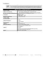
Страница 5: ...n and Viton Maximum Allowable Operating Pressure 1440 psig 20 F to 120 F 99 barg 28 C to 48 C Connections Pipeline MNPT Sample Outlet MNPT Regulator Output Range 50 100 psig 3 6 barg Insertion Length 8 Insertion Diameter Electrical Connection DC 6 V DC 12 V DC 24 V Standard Sample Volume 0 25 cc Operation Piston Operated Pump Enclosure Dimensions 10 x 8 x 4 Height x Width x Depth Features Polycarb...

Страница 6: ...4 Equipment Diagrams Figure 1 Standard Essentials Gas Sampler Diagram 6 IOM 222 MODEL ESSENTIALS GAS SAMPLER REV A 13839 West Bellfort Street Sugar Land TX 77498 welker com Service Department 281 491 2331 ...

Страница 7: ...ure 2 Essentials Gas Sampler With Optional Welker 6Tc Timer Controller 7 IOM 222 MODEL ESSENTIALS GAS SAMPLER REV A 13839 West Bellfort Street Sugar Land TX 77498 welker com Service Department 281 491 2331 ...

Страница 8: ...ere the product is well mixed and will yield an accurate and representative sample 2 The sample probe should be located in the least turbulent area of the flowing stream i e not in a header or blow down stack and away from obstructions elbows and partially closed valves 2 2 Preparing for Installation To watch a short video of these instructions scan the QR code below orgo to welker com videos Esse...

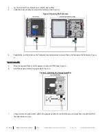
Страница 9: ... Figure 4 Gauge Assembly 5 Wrap the exposed threads on the gauge assembly with PTFE tape Figure 3 6 Install the gauge assembly to purge valve B Figure 5 Figure 5 Installing the Gauge Assembly 7 Using a crescent or pipe wrench tighten the gauge assembly Ensure that the pressure gauge face is upright and that the tube elbow is on top 9 IOM 222 MODEL ESSENTIALS GAS SAMPLER REV A 13839 West Bellfort S...

Страница 10: ...n the bottom of the enclosure to seal the port 10 Insert each end of the tubing assembly into the appropriate tube elbow The bottom of the tubing assembly should connect to the tube elbow in the gauge assembly The top of the tubing assembly should connect to the tube elbow at the sample outlet of the WelkerMPS 2Micropurge Sample Pump 11 Use a wrench to tighten the ends of the tubing into the tube ...

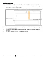
Страница 11: ...Determining the Insertion Depth 13 Beginning at the tip of the sample probe measure along the probe to the desired insertion depth Figure 1 or Figure 2 Use a felt tip pen to mark this point 14 Using tubing cutters remove the excess tubing at the marked point and then file and smooth the cut edge of the sample probe 15 The Essentials Gas Sampler is now ready to be installed to the pipeline 11 IOM 2...

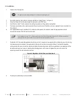
Страница 12: ...ble Logic Controller will be used to referto the PLC EFM flow computer or othersignal control system used by the customerto activate and operate the solenoid 7 The Welker IR 7 Instrument Regulator comes factory set to 50 psig and is equipped with a relief valve pre set to 85 psig to relieve pressure and protect the equipment in the case of a seal leak or regulator failure To adjust the regulator s...

Страница 13: ...ding and that sample cannot flow to the sample cylinder If the inline relief does not need to be adjusted continue to step 5 If the inline relief requires adjustment proceed to Section 3 3 Adjusting the Inline Relief The inline relief comes factory set to 1100psig The inline relief should not require adjustment unless pipeline pressure drops below 400psig ormaintenance is performed on the inline r...

Страница 14: ...ead screwdriver press and release the solenoid test button every 5 seconds to actuate the MPS 2 and build pressure Figure 9 With each actuation a pressure increase should be observable on the outlet pressure gauge 12 If pressure is holding continue to step 13 If pressure has dropped check for leaks and repair as necessary If an increase in pressure is observed without manually actuating the soleno...

Страница 15: ...valve on the sample cylinder and purge valve B are closed Preparing for Sampling 16 As necessary program the Welker 6Tc Timer Controller Figure 2 Refer to the Installation Operation and Maintenance IOM Manual for the 6Tc for instructions on setting the 6Tc 17 As necessary set the PLC to the desired sampling frequency based on the sampling actuation equations provided Figure 10 Figure 10 Gas Sampli...

Страница 16: ...sampling until the desired volume of sample has been obtained Removing the Sample Cylinder 7 De energize the solenoid to stop actuating the MPS 2 and halt sampling 8 Close the inlet valve on the sample cylinder 9 Loosen the tube fitting on the inlet of the sample cylinder to allow the trapped gas to vent and then tighten the tube fitting 10 Disconnect the sample cylinder from the sample outlet 11 ...

Страница 17: ... on parts Wipe excess lubricant from the seals as it may adversely affect analytical instrument results Forsample exposed seals Welkerrecommends non hydrocarbon based lubricants such as Krytox Fornon sample exposed seals Welkerrecommends eithernon hydrocarbon based lubricants orsilicone based lubricants such as Molykote 111 Afterthe seals are installed the outerdiameterof shafts and innerdiametero...

Страница 18: ...manual 5 After performing necessary maintenance on system components reconnect all instrument tubing 6 Maintenance is now complete See Section 2 3 Installation and Section 2 4 Start Up Procedures for instructions on returning the Essentials Gas Sampler to operation If maintenance is performed on the MPS 2 the inline relief needs to be reset Welkerrecommends setting the inline relief to 1100 psig u...

Страница 19: ...unterclockwise until some gas bleeds through 6 Turn the spring adjuster clockwise until no gas bleeds through and then turn the spring adjuster clockwise another full turn Ensure that at least half a turn remains on the spring adjuster as too much tension will prevent the spring from contracting and releasing when the MPS 2is actuated To ensure at least half a turn remains on the spring adjuster W...

Страница 20: ...ugh 17 Turn the spring adjuster counterclockwise until some gas bleeds through Ensure that at least half a turn remains on the spring adjuster as too much tension will prevent the spring from contracting and releasing when the MPS 2is actuated To ensure at least half a turn remains on the spring adjuster Welkerrecommends turning the spring adjusterclockwise and counting each turn until the spring ...

Страница 21: ...mple cylinder is open Check all fittings from the sample outlet to the inlet valve on the sample cylinder for leaks Repair as necessary See Section 2 4 Start Up Procedures for instructions on setting the inline relief See Section 2 4 Start Up Procedures for instructions on testing the MPS 2 and ensuring that the sampler will build pressure The sample cylinder is filling too quickly The inline reli...

Страница 22: ...ges Welker IOM V274 l Versa Products Company Inc C Series Solenoid Valves Welker IOM V041 l Versa Products Company Inc CSG 4222 LA XX D012 Solenoid Valve Welker IOM V071 l WIKA Instrument Corporation Bourdon Tube Pressure Gauges Type 232 53 and Type 233 53 Welker IOM V171 Welker drawings and schematics suggested for use with this unit l Assembly Drawing AD681BK Standard Essentials Gas Sampler l As...

Страница 23: ...adjust the regulator setting 4 Install the inlet valve of the sample cylinder to the sample outlet on the Essentials Gas Sampler Start Up Procedures 1 With all valves shut pressurize the pipeline 2 Test the Essentials Gas Sampler 3 Purge the sample cylinder 4 Program the timer or controller to the desired sampling frequency The numberof times the solenoid should be energized during the sample peri...

Страница 24: ..._________________________________________ ____________________________________________________________________________________________________ ____________________________________________________________________________________________________ ____________________________________________________________________________________________________ _______________________________________________________...

Отзывы:

Похожие инструкции для ESSENTIALS AD681BK