background image

Manual R06-2016

124 / 172

ROTARY INDEXING TABLE CONTROLLER EF2...B 

OPERATION / DESCRIPTION OF WEISS SOFTWARE | 

8.5 Operation and Monitoring

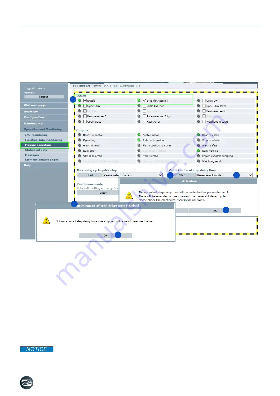
8.5.3.4 Manual operation: Optimization of stop delay time

Condition for manual operation: The control authority has to be activated.

The control authority of the browser window is indicated by the yellow and black frame around the input field.

The Optimization of stop delay time should always be carried out after the Measuring cycle quick stop.

Fig. 74: Manual operation: Optimization of stop delay time

The "Optimization of stop delay time" function is used to determine the optimal starting position on the position cam.

1. Set the inputs "Enable" and "Stop (low-active)".

These two inputs have to be set in order to enable manual operation.

2. Select mode.

Measurement - only CW

Measurement - only CCW

Alternating

3. Start the "Optimization of stop delay time" function.

Confirm messages in the following windows that open up.

The determined stop delay time will be displayed in the dynamic parameters (chapter 8.3.6 „Dynamic parame-
ters“ on page 107)
.

4. After finishing manual operation: Release control authority.

Changes

The function needs to be repeated for every change of the rotary indexing table (e.g. change of load).

3.

2.

1.

4.

4.

5.

Содержание 3RT2017-1BB42

Страница 1: ...MANUAL ELECTRICAL SYSTEM DOCUMENTATION ROTARY INDEXING TABLE CONTROLER EN_06_2016 EF2 ...

Страница 2: ...troller Type EF2 B This document has been prepared by WEISS GmbH Siemensstrasse 17 D 74722 Buchen Copyright All rights in this document are the copyright of WEISS GmbH This document may not be copied or reproduced in whole or in part without the written permission of WEISS GmbH This document is only intended for the user of the product described and may not be passed on to third parties in particu...

Страница 3: ...azards 16 3 COMPONENT DESCRIPTIONS 18 3 1 Power Modules PM240 2 18 3 1 1 Safety instructions 18 3 1 2 Power Module PM240 2 frame size FSA 19 3 1 3 Power Module PM240 2 frame size FSB 20 3 1 4 Technical data 21 3 1 5 Overview Power Module PM240 2 23 3 2 External braking resistor option 24 3 2 1 Technical data 24 3 3 Motor contactor 25 3 3 1 Technical data 25 3 4 Safety relay 26 3 4 1 Technical data...

Страница 4: ...ize FSA FSB 55 6 2 1 Dimensions hole patterns 56 6 2 1 1 Frame size EF2037 to EF2220 56 6 2 1 2 Frame size EF2300 57 6 2 2 Mounting the shielding plate 58 6 2 3 Mounting Connecting the power module 59 6 2 4 EMC compliant installation 60 6 2 4 1 Power mains connection 1 AC 200 V 240 V 0 37 kW 61 6 2 4 2 Power mains connection 3 AC 380 V 480 V 1 5 kW 62 6 2 4 3 Power mains connection 3AC 380 V 480 V...

Страница 5: ...ile 111 8 4 1 1 Request diagnostic file 111 8 4 1 2 Request configuration file controller internal backup file 112 8 4 2 Licenses 113 8 4 3 User manager 114 8 5 Operation and Monitoring 115 8 5 1 I O monitoring 115 8 5 1 1 Monitoring inputs and outputs 115 8 5 1 2 Forcing via the Request authority of control button 116 8 5 1 3 Forcing via the Open separate user screen button 117 8 5 2 Fieldbus dat...

Страница 6: ... Power Module connection example 154 13 1 5SIL3 D410 2 Interface I O connection example 155 13 1 6SIL3 Safety relais connection example 156 13 1 7SIL3 Interface I O Module TM15 option connection example 157 13 2 EF2 B 1 5 kW to 3 0 kW Controllers connection examples 158 13 2 1SIL2 Power Module connection example 158 13 2 2SIL2 D410 2 Interface I O connection example 159 13 2 3SIL2 Interface I O Mo...

Страница 7: ...ted safety function SIL2 PLd SIL3 PLe available with additional measures 1 2 Intended use The components for the controller and drive are approved for industrial and commercial application in industrial mains supply All information regarding the technical data and the permissible conditions at the location of use must be complied with Commissioning starting the intended operation of the machine in...

Страница 8: ...al modules Their assembly and wiring are the responsibi lity of the user Pos Component Type Characteristics 1 Control unit SIMOTION D410 2 2 3 Power module PM240 2 frame size FSA frame size FSB 4 External Braking resistor Koch Option 5 Module TM15 Option for digital inputs outputs 6 Motor contactor Option for applications up to SIL3 PLe 7 Safety relay Option for applications up to SIL3 PLe 1 4 2 3...

Страница 9: ...XING TABLE CONTROLLER EF2 B INTRODUCTION 1 4 Controller components Fig 2 Block diagram of EF2 B controller with PM240 2 FSA PM240 2 FSA L1 L2 L3 Ethernet Digital I O 24 VDC Fieldbus Profibus Profinet TC TR PM IF 24 VDC Safe Brake Relay ...

Страница 10: ...XING TABLE CONTROLLER EF2 B INTRODUCTION 1 4 Controller components Fig 3 Block diagram of EF2 B controller with PM240 2 FSB PM240 2 FSB L1 L2 L3 Ethernet Digital I O 24 VDC Fieldbus Profibus Profinet TC TR PM IF Safe Brake Relay 24 VDC ...

Страница 11: ...is manual describes the handling of the machine and contains important instructions and information to assist you in correct use of the machine A PDF file with these instructions is also available on the CF card of the controller Safety instructions in individual chapters should be observed The manual is to be kept for further use and must be handed over to subsequent owners users or end customers...

Страница 12: ... Indicates a list Indicates the second level of a list The book symbol before a section of text indicates further applicable documents The information symbol before a section of text marks an additional note or an important tip for use 1 6 5 Figures The figures used show the parts of the controller as examples There may be differences between the illustrations and the actual delivered controller 1...

Страница 13: ...erve the specified danger and warning notices 2 1 1 Operator s obligation to exercise diligence The operator must ensure that The controller and the machine controlled by it are only used as intended The controller and the machine controlled by it are only operated in perfect working condition and the mechanical and electrical safety equipment are present this manual and all other applicable docum...

Страница 14: ...tion packaging correct long term storage in the transport packaging proper setup and installation as well as careful operation and mainte nance In addition to the danger and warning information provided in the technical customer documentation the applicable national local and system specific regulations and requirements must also be taken into account To ensure compliance with EN 61800 5 1 and UL ...

Страница 15: ...necessary They must only be handled on the front panel or in the case of circuit boards at the edge Electronic modules must not come into contact with plastics or items of clothing containing synthetic fibres Electronic modules must only be placed on conductive surfaces work surfaces with ESD surface conductive ESD foam ESD packing bag ESD transport container Do not place electronic modules near d...

Страница 16: ... immediate vicinity of the controller External influences damage Extreme temperatures as well as emissions of light noise particles or gases caused by for example Component malfunctions Software errors Operating and or ambient conditions which are not within the scope of the specification External influences damage Hazardous shock voltages caused by for example Component malfunctions Influence of ...

Страница 17: ...om it and applied in order to reduce dangers and their impact on persons and that exposure and danger zones must be defined and observed The relevant safety instructions in each chapter must be observed Danger to life due to high leakage currents if the external protective conductor is interrupted The drive components generate a high leakage current trough the protective conductor Touching conduct...

Страница 18: ... operated in cabinets or in closed electrical operating areas and must be connected with the protective conductor In order to provide protection against electric shock the protective conductor connection on the cabinet or machine must be implemented in accordance with one of the following measures Fixed connection and protective conductor connection with cross sectional areas 10 mm 2 Cu or 16 mm 2...

Страница 19: ... bottom side of the power module Refer to the device manual of the manufacturer for further information Pos Interface Description 1 L N Power mains connection 2 PE Protective ground connection for the line supply cable 3 DCN DCP DC bus negative DC bus positive 4 DCP R2 Braking resistor connection 5 PE Protective ground connection for the motor cable 6 U2 V2 W2 Motor connection 7 PM IF Power module...

Страница 20: ...ottom side of the power module Refer to the device manual of the manufacturer for further information Pos Interface Description 1 L1 L2 L3 Power mains connection 2 PE Protective ground connection for the line supply cable 3 DCN DCP DC bus negative DC bus positive 4 DCP R2 Braking resistor connection 5 PE Protective ground connection for the motor cable 6 U2 V2 W2 Motor connection 7 PM IF Power mod...

Страница 21: ... 4 4 4 Efficiency factor η 0 96 0 97 0 96 0 97 0 96 0 97 0 96 0 97 Power loss 3 at rated current kW 0 04 0 077 0 103 0 128 Cooling air requirement m 3 s 0 005 0 005 0 005 0 0092 Sound pressure level LpA 1 m dB 50 50 50 62 24 V DC supply for the control unit A 1 0 1 0 1 0 1 0 Input current 4 Rated current 1AC 3AC based on IH 1AC 3AC Rated current based on IH A A A A 7 5 4 3 6 6 3 8 7 7 6 1 10 1 8 8...

Страница 22: ... are based on the load cycle for low overload LO 2 The base load current IH is based on the load cycle for high overload HO 3 Typical values Further information in the Internet at http support automation com WW view de 94059311 4 The input current depends on the motor load and network impedance The input currents are valid for loading with rated power based on IN at a network impedance according t...

Страница 23: ... or to Control Unit Adapter Line filter 1 To achieve EMC Category C1 Fuses OPTION Power choke Fuses L1 L2 L3 PE L1 L2 L3 2L1 2L2 2L3 2PE 1L1 1L2 1L3 1PE 2L1 2N 2PE 1L1 1N 1PE 2 OPTION Motor choke 1U1 1V1 1W1 PE1 1U2 1V2 1W2 PE2 Braking resistor 3 1 Only for PM240 2 without integrated line filter 2 Only for PM240 2 with integrated line filter 3 Connection to braking resistor has to be shielded OPTI...

Страница 24: ... Refer to the device manual of the manufacturer for further information Order number EF2037B BWD250390K01R0901SI EF2150B EF2220B BWD500150K01R0901SI EF2300B BWD600080K01R1002SI Suitable for power modules of frame size FSA FSB Peak power Pmax kW 1 5 2 5 4 0 Resistance Ω 390 150 80 Tolerance resistance value 5 at room temperature Tolerance coefficient TC 20 100 at 10 6 K Insulation resistance RISO M...

Страница 25: ...facturer for further information 1 Coil terminal on the front side 2 Openings for voltage tap of the main circuit communication capable power contactor only 3 Location hole for surge suppression 4 Location hole for 1 2 and 4 pole auxiliary switch blocks 5 Labelling plate 6 1 integrated auxiliary contact 1 normally closed contact 7 Main circuit terminals of the contactor to the load motor connectio...

Страница 26: ... The internal electronics and firmware are checked for proper function during that During the operation all internal safety critical circuit elements are cyclically monitored for faults During this the semi conductor outputs are checked cyclically for correct function by a light dark test of max 2 5 ms length dynamic The safety relays are designed so that applications can be realised up to SIL3 ac...

Страница 27: ...levation above sea level 2 000 m Vibration resistance in accordance with IEC 60068 2 6 5 500 Hz 0 75 mm Degree of contamination 3 Overvoltage category III Spacing to be maintained during serial installation to the side 0 mm Spacing to be maintained to grounded components to the side 5 mm DCavg average diagnostic coverage 99 MTTFd Mean Time To a dangerous Failure 30 years Equipment identification A...

Страница 28: ...has a separate 24 V supply In the case of the EF2 option DI DO the TM15 terminal module is delivered with an included a DRIVE CLiQ cable Fig 11 Interfaces of the TM15 Terminal Module Refer to the device manual of the manufacturer for further information Pos Interface Description 1 X501 DRIVE CLiQ interface 2 X500 DRIVE CLiQ interface 3 X524 Electronics power supply 4 LED Status indicator 5 X520 8 ...

Страница 29: ... to the device manual of the manufacturer for further information Pos Interface Description 1 Connection for the solenoid of the motor brake 2 Connection for a 24 V DC power supply 3 Connection for the cable harness CTRL to the power module blocksize format included in the scope of deli very Pos Inter face Description Power supply DC 20 4 to 28 8 V Recommended nominal value of the power supply 26 ...

Страница 30: ...Manual R06 2016 30 172 ROTARY INDEXING TABLE CONTROLLER EF2 B COMPONENT DESCRIPTIONS 3 6 Brake Relay 3 6 2 Brake Relay connection example Fig 13 Brake Relay connection example Brake Relay ...

Страница 31: ...are run on shared control hardware SIMOTION D410 2 is a compact control unit predestined for single axis applications The SIMOTION D410 2 Control Unit is mounted directly on to the Power Module PM240 2 The firmware and preset parameters for operation are stored on a CF card that has to be inserted into the slot on the Control Unit D410 2 The control unit communicates with external components via t...

Страница 32: ...solated digital input Fail safe digital output 10 X131 High speed digital inputs outputs Analog input 11 X127 Service interface System data dimensions weight Dimensions W x H x D 73 x 190 7 x 74 4 mm Permissible temperature range Storage Operation 25 C 55 C 0 C 55 C Protection class IP 20 EN 60529 Protection class Class I with protective conductor connection and class III PELV acc to EN 61800 5 1 ...

Страница 33: ...to the front of the device 3 7 3 CompactFlash Card The CompactFlash card is mandatory for operation of the SIMOTION D410 2 The SIMOTION Kernel SIMOTION D410 2 firmware and the software used to control the drives WEISS firmware are stored on the CompactFlash card 1 Data matrix code 2 Module designation 3 Order number 4 Ethernet interface MAC address of X127 5 PROFINET IO interface MAC address of X1...

Страница 34: ...ion CCW A LOW HIGH edge starts one cycle Cycle CW level Bit 4 With this command the rotary indexing table starts one cycle in the direc tion of rotation CW The signal must be present the entire time during the movement and should only be reset when the signal In operation is reset Resetting the signal during rotation leads to an immediate stop A restart outside of the position cam is carried out w...

Страница 35: ...and sent back to the superordinate controller This signal can be monitored by the superordinate controller A flashing cycle or a static HIGH signal can be used for example as a monitoring signal Jog CW Not allocated As long as this signal is HIGH the rotary indexing table will rotate CW with Parameter set 3 Jog CCW Not allocated As long as this signal is HIGH the rotary indexing table will rotate ...

Страница 36: ...stop delay or stop ramp that was set in order to reach an optimal starting position for the next cycle If however this output signal is LOW then processing must be stopped immediately because the rotary indexing table has left its position Stop selected Bit 3 Direct feedback from the Stop input Alarm timeout Bit 4 The rotary indexing table did not reach the next locking position within the specifi...

Страница 37: ...EF2 by the superordinate controller A signal can be specified by the superordinate controller via Receive watchdog This signal is copied in the EF2 onto the Send watchdog signal and sent back to the superordinate controller This signal can be monitored by the superordinate controller A flashing cycle or a static HIGH signal can be used for example as a monitoring signal Signal Default configuratio...

Страница 38: ...I 6 DI 7 DI 7 M 1 M 1 M 2 M 2 DO 15 DO 15 DO 14 DO 14 DO 13 DO 13 DO 12 DO 12 DI 11 DI 11 DI 10 DI 10 DI 9 DI 9 DI 8 DI 8 L2 L2 X521 X521 M 3 M 3 DO 23 DO 23 DO 22 DO 22 DO 21 DO 21 DO 20 DO 20 DO 19 DO 19 DO 18 DO 18 DO 17 DO 17 DO 16 DO 16 L3 L3 X522 X522 24 DC 24 DC PE PE DI 0 DI 0 DI 1 DI 1 DI 2 DI 2 DI 3 DI 3 DI 4 DI 4 DI 5 DI 5 DI 6 DI 6 DI 7 DI 7 DI 8 DI 8 DI 9 DI 9 DI 10 DI 10 DI 11 DI 11 ...

Страница 39: ...al The Stop selected feedback switches to LOW The Ready to start feedback switches to HIGH as soon as the rotary indexing table is released and Stop low active is HIGH c If the feedback Ready to start is HIGH the rotary indexing table can be cycled by the control signal Start cycle CW The Start cycle CW control signal has to be set only for one EF2 control cycle and can then be taken back immediat...

Страница 40: ...start feedback switches to HIGH as soon as the rotary indexing table is released and Stop low active is HIGH c If the feedback Ready to start is HIGH the rotary indexing table can be cycled by the control signal Start level CW The control signal needs to be set for the total time of the cycle otherwise the current cycle is interrupted d At this time the external processing can be started The cycle...

Страница 41: ...ied with there is a risk of electric shock 1 Reference potential for DI 17 DI 19 DI 21 or F DI 0 to F DI 2 second shutdown path 2 Functionality depends on the parameterized Safety Integrated functions The functionality of the digital inputs DI 16 to DI 21 depends on the parameterized Integrated Safety functions Representation Pin Name Description 1 Temp Do not use 2 Temp 3 F DI 0 2 DI 16 STO 24 V ...

Страница 42: ...er supply When using external power supplies e g SITOP the ground potential has to be connected with the protective con ductor connection PELV Representation Pin Name Description 1 DI 0 Motor temperature switch 2 DI 1 HW limit switch CW low active 3 DI 2 HW limit switch CCW low active 4 DI 3 Motor contactor feedback 5 M2 Ground reference for DI 0 DI 3 6 M Ground reference of the electronics 1 7 DI...

Страница 43: ...nput 2 Reference potential for DI 20 3 The proper function of the DO 16 requires that the terminals 5 6 are connected 4 F DO 0 for Safety Integrated extended functions 5 For applications without safety function DO 16 does not function An open input is interpreted as LOW If M1 or M2 is connected with M the electrical isolation no longer exists Representation Pin Name Description 1 DI 22 Do not use ...

Страница 44: ...ct results may occur during analog digital conversion A 24 V supply voltage must be connected to terminal X124 for the digital outputs to be used If momentary interruptions in the voltage occur in the 24 V supply the digital outputs will be deactivated in the mean time Representation Pin Name Description 1 DI DO 12 Feedback 24 V power supply of brake relay 2 DI DO 13 Do not use 3 M Do not use 4 DI...

Страница 45: ...ust always be connected if at least one DI DO in the potential group is used as an output M1 A ground reference for DI DO 0 to 7 first potential group must always be connected if at least one DI DO in the potential group is used as an output DI DO Digital input output Representation Terminal Name 1 L2 2 DI 8 3 DI 9 4 DI 10 5 DI 11 6 DO 0 7 DO 1 8 DO 2 9 DO 3 10 M2 GND Screw terminal Max connectabl...

Страница 46: ... 9 8 DO 10 9 DO 11 10 M3 GND Screw terminal Max connectable cross section 1 5 mm 2 L3 A 24 V DC power supply for DI DO 16 to 23 third potential group must always be connected if at least one DI DO of the potential group is used as an output M3 A ground reference for DI DO 16 to 23 third potential group must always be connected if at least one DI DO of the potential group is used as an output DI DO...

Страница 47: ... 5 2 Extended safety functions SIL3 The safety category SIL3 according to IEC 61508 can be fulfilled by the application of additional measures Additional motor contactor Safe brake control by means of a safety relay Contactor with mirror contact forced and feedback to the safety relay Fig 18 SIL 3 Basic concept Evidence of SIL 3 capability can be demonstrated with the Siemens Evaluation Tool SET w...

Страница 48: ...Manual R06 2016 48 172 ROTARY INDEXING TABLE CONTROLLER EF2 B SAFETY FUNCTIONS 5 2 Extended safety functions SIL3 Fig 19 SET screen Calculation for FC Fig 20 SET screen Calculation for motor contactor ...

Страница 49: ...ncy off S1 the drive is first brought to a standstill t1 on an unsafe quick stop ramp by means of the Quick stop function After a delay time t2 which is set in the safety relay the safety relay activates the STO function in the drive and the motor contactor is separated If the drive does not come to a standstill in the available shutdown time t1 then it might not be possible to prevent the motor c...

Страница 50: ...ing channels of the integrated safety functions of the SINAMICS S120 It is automatically carried out by selecting deselecting the STO function A message is displayed for this Safety monitoring error When a safety error occurs such as simultaneity monitoring the drive will come to a standstill by coasting down on its own The correct operation of the safety device must be confirmed afterwards e g by...

Страница 51: ... braking resistor must be connected to con vert the generated power into heat 6 1 1 Dimensions hole patterns Fig 22 Dimensions BWD250 283 241 48 186 10 70 9 7 10 70 8 90 137 110 266 143 98 186 62 3 160 13 85 61 160 7 20 60 64 60 45 51 14 R 3 R 3 R5 Sticker on both sides M4 M4 designed for DIN rail clamping bracket M4 x x x View with premounted DIN rail clamping brackets 90 45 25 4 5 40 9 5 x Tempe...

Страница 52: ... 10 70 8 90 31 216 266 37 204 186 62 3 160 13 85 61 160 7 20 60 64 60 45 51 14 R 3 R 3 R5 M4 M4 M4 x x x 90 45 25 4 5 40 9 5 x Sticker on both sides designed for DIN rail clamping bracket View with premounted DIN rail clamping brackets Temperature switch up to 200 C View with premounted screws to fix the frequency inverter with hole pattern 186 62 3 QS sticker ...

Страница 53: ... 60 288 246 186 10 80 9 7 8 100 36 216 30 271 42 204 80 10 7 40 70 42 4 5 70 14 51 51 R 3 R 3 R5 x x x x x 53 M4 80 Sticker on both sides designed for DIN rail clamping bracket View with premounted DIN rail clamping brackets Temperature switch up to 200 C View with premounted screws to fix the frequency inverter with hole pattern QS sticker ...

Страница 54: ... have already been made in the brake resistor The screws are supplied Ensure sufficient ventilation 3 Connect the cable of the brake resistor to the terminals DCP and R2 of the power module PM240 2 The plug connections are located on the bottom side of the power module The temperature monitor of the brake resistor can be connected optionally and monitored Fig 25 Braking resistor connection on the ...

Страница 55: ...control cabinet The control cabinet requires a cooling air flow to protect the components against overheating Refer to the Siemens installation manual for calculation of the cooling air flow Cooling air short circuits need to be prevented by the installation of appropriate air guide plates Mount the power module vertically with the mains and motor connections downwards Fig 26 Installation position...

Страница 56: ...t Power module brake resistor and shielding plate have different hole patterns WEISS GmbH recommends drilling the boreholes for all three components during the installation This way further drilling possible interferences due to metal chips and mechanical loads are avoided during an eventual retrofitting A Ventilation clearance B Braking resistor C Shielding plate A B B B C C 62 3 2 45 186 7 32 6 ...

Страница 57: ...ake resistor and shielding plate have different hole patterns WEISS GmbH recommends drilling the boreholes for all three components during the installation This way further drilling possible interferences due to metal chips and mechanical loads are avoided during an eventual retrofitting A Ventilation clearance B Braking resistor C Shielding plate A B B B M4 FSB M4 M4 291 11 46 165 6 5 225 8 86 28...

Страница 58: ...te The shielding plate and the fastening screws are included in the accessory bag of the convertor Shielding plate and safe brake relay have already been factory fitted Fig 30 Mounting the shielding plate 1 Pull off the motor connection plug 2 Positioning the shielding plate 3 Screwing on the shielding plate 4 Plug in the motor connection plug 2 1 3 4 ...

Страница 59: ...for power modules The following clearances must be observed between the components when mounting1 Frame size FSA 30 mm 1 18 inch Frame size FSB 40 mm 1 57 inch The following cooling clearances must be observed above and below the device Frame sizes FSA and FSB above 80 mm 3 15 inch Frame sizes FSA and FSB below 100 mm 3 93 inch The following cooling clearances must be observed in front of the devi...

Страница 60: ... Motor and motor temperature sensor Brake resistor Fieldbus Brake line Inputs and outputs of the terminal strip Attaching cable shields for EMC compliance Fig 31 EMC compliant shield connection EMC compliant wiring for mains and motor connection as well as for the control unit 1 Mains line unshielded with strain relief by cable binders 2 Shielded motor line with hose clamp for shielding and strain...

Страница 61: ...fter each shutdown wait five minutes before switching it on again The plug connections are located on the bottom side of the power module Fig 33 Power mains connection 1 AC 200 V 240 V 0 37 kW Name Power mains connection plug Release lever L1 Line phase L N Line phase N PE Protective ground Class J UL safety fuses Rated current 10 A Screw terminals Cross section Tightening torque Stripping length ...

Страница 62: ...ore switching it on again The plug connections are located on the bottom side of the power module Fig 34 Power mains connection 3 AC 380 V 480 V 1 5 kW Name Power mains connection plug Release lever L1 External conductor L1 L2 External conductor L2 L3 External conductor L3 PE Protective ground Class J UL safety fuses Rated current 10 A Safety fuses NH Rated current 10 A Screw terminals Cross secti...

Страница 63: ... again The plug connections are located on the bottom side of the power module Fig 35 Power mains connection 3AC 380 V 480 V 2 2 3 0 kW Name Power mains connection plug Release lever L1 External conductor L1 L2 External conductor L2 L3 External conductor L3 PE Protective ground Class J UL safety fuses Rated current 10 A 2 2 kW 12 A 3 0 kW Safety fuses NH Rated current 10 A 2 2 kW 16 A 3 0 kW Screw...

Страница 64: ...p angle Use low capacitance cables Core core 75pf m Core shield 150pf m An EMC screw connection must always be used for the shield contact on motors with metal terminal box The shield must be connected to the PE screw on motors with plastic terminal box Fig 36 Connecting the motor cable to the motor The following measures are absolutely necessary to avoid EMC problems Cable for the holding brake A...

Страница 65: ...he range of 25 150 of the converter output are permissible without restrictions for 400 V Power Modules 6 2 5 2 Motor connection PM240 2 frame size FSA The plug connections are located on the bottom side of the power module Fig 37 Motor connection PM240 2 frame size FSA Name Motor connection plug Release lever U2 Motor phase U V2 Motor phase V W2 Motor phase W Protective ground Screw terminals Cro...

Страница 66: ...he power module Fig 38 Motor connection PM240 2 frame size FSB Name Motor connection plug Release lever U2 Motor phase U V2 Motor phase V W2 Motor phase W Protective ground Screw terminals Cross section Tightening torque Stripping length 1 5 to 6 0 mm2 0 6 mm 8 0 mm Motor terminal block with star bridge Motor terminal block with delta bridge For terminal identifications refer to terminal block lid...

Страница 67: ...late 2 Mount the shielding plate with brake relay on the power module Shielding plate assembly see chapter 6 2 2 Mounting the shielding plate on page 58 3 Insert the cable of the brake relay into the socket on the brake relay 4 Remove the CPU module from the power module 5 Insert the cable of the brake relay into the Safe Brake terminal 6 Route the cable of the brake relay through the channel in t...

Страница 68: ...fety relay 6 4 1 Mounting Safety Relay 3SK1122 1CB41 Fig 40 Mounting Safety Relay 3SK1122 1CB41 The safety relay is designed to be mounted on a DIN rail 1 Latch the safety relay onto a DIN rail 2 Note the dimensions according to the illustration 3 Regard the required cooling and mounting clearances ...

Страница 69: ...inal Module TM15 6 5 1 Mounting Terminal Module TM15 Fig 41 Mounting Terminal Module TM15 The Terminal Module TM15 is designed to be mounted on a DIN rail 1 Mount the Terminal Module TM15 on to a DIN rail 2 Note the dimensions according to the illustration 3 Regard the required cooling and mounting clearances ...

Страница 70: ...410 2 The SIMOTION D410 2 Control Unit is mounted directly on to the Power Module PM240 2 1 Attach the control module to the recesses of the power module using the hooks 2 Press the control module against the power module The blue latch must snap into place Disassembly of the control unit Fig 43 Mechanical disassembly of Control Unit D410 2 1 Press the blue latch down 2 Swivel the control unit to ...

Страница 71: ...ol Module 1 Align the CF card 1 according to the arrows 2 There is one arrow 2 on the plug in slot and on the CF card 2 Insert the CF card gently into the empty slot 3 of the SIMOTION D410 2 until it snaps in When properly inserted the CF card is flush with the housing NOTICE The CompactFlash card may only be inserted or removed while the SIMOTION D410 2 Control Unit is in a de ener gized state Th...

Страница 72: ...fter the cable entry point in the cabinet Strip the isolation off the cable first 2 Continue routing the shielded cable up to the module but do not make the connection to the shield there Using a shield connection on the SIMOTION D410 2 1 Unscrew the holding clamp of the M3 shield connection Torx screwdriver T10 at the top of the SIMOTION D410 2 until there is a space below the clamp 2 Insert the ...

Страница 73: ...o to SYSTEM PROPERTIES CONTROL PANEL INTERNET OPTIONS CONNECTIONS LAN SETTINGS and make the following settings Activate Automatically detect settings Deactivate Use a proxy server for your LAN It is necessary to adjust the Internet settings or network settings on the PC or notebook Fig 47 Adjusting the Internet options Should it not be possible to establish a connection using these settings then t...

Страница 74: ...llowing settings Clear if selected the check box in front of Internet Protocol Version 6 TCP IPv6 Select Internet Protocol Version 4 TCP IPv4 Double click Internet Protocol Version 4 TCP IPv4 Configure a higher or lower IP address than the standard IP of the controller e g IP address 169 254 11 21Subnet mask 255 255 0 0 Fig 48 Changing the adapter settings Default IP address of the EF2 controller ...

Страница 75: ...address of the device is created and stored on the computer This pro cess remains hidden for the user which is done automatically so that the use of this protocol is only noticeable when a communication error occurs The validity period of an ARP address can become a problem if there are incorrect entries or entries which are no longer valid As long as the incorrect entry exists it is not possible ...

Страница 76: ...ss of the controller and confirm with ENTER If all presettings were made correctly as described in chapter 7 1 then the start page of the controller will appear See chapter 8 1 Start page on page 77 An error message is displayed in case of a faulty input of an IP address or a wrong configuration Fig 49 Error message website Check the IP address and correct if an erroneous entry had been made Check...

Страница 77: ... Connection active green yes grey no Startup done green yes grey no Indexer configured green yes grey no Quick stop monitoring green yes grey no Delay time optimised green yes grey no Rotary indexing table state e g WAIT_FOR_ENABLE The login options need to be entered in the login area User name Password In the Navigation area you can navigate among the available menus Start page Overview Configur...

Страница 78: ...ation D Information Selection Area Topic Section Status indicator Controller Green Action successfully completed Grey Action not executed yet Rotary indexing table Rotary indexing table state e g WAIT_FOR_ENABLE Login Certain sections in the user interface are reserved for authorized personnel A user name and password have to be entered to access these sections Each controller comes with a user na...

Страница 79: ...word manage user groups Operation and Moni toring see chapter 8 5 I O monitoring of the inputs and outputs Fieldbus data monitor Manual operation Statistical data Messages Siemens default pages only for WEISS Service personnel Help see chapter 8 6 Contact details for WEISS GmbH Documentation manuals from WEISS SIEMENS GSD files Information Sel ection Information and comments about the indexer conf...

Страница 80: ...tion and the system data Useful data is only displayed on this page after a rotary indexing table has been configured The content on the Overview page is informative and cannot be changed on this page Exception By clicking the RESET button next to Batch Counter the count will be set to zero Available information Rotary indexing table state e g WAIT_FOR_ENABLE Operational status Time measurements S...

Страница 81: ...roller and cannot be changed The default IP setting can be used to restore the initial setting Setting the default IP If the user operator does not know the IP configuration of a rotary indexing table the controller cannot be acces sed In this case the default IP configuration 169 254 11 22 for the Ethernet interface can be activated by connecting 24 VDC to input DI10 terminal X121 10 This known I...

Страница 82: ...er 8 3 5 I O configuration on page 89 Access to the entire indexer configuration is only permitted for authorised persons User name and password are supplied with the controller chapter 8 1 2 Login on page 79 8 3 2 Reset factory settings When upgrading the WEISS firmware the factory settings always need to be reset before starting the configuration If an internal firmware update should be carried ...

Страница 83: ...ect data file Display input field for data file Select type of indexer options Confirmation Decline I O configuration Input comment for data file Select data file Data file selected Display input field for data file I O configuration from file I O Mapping interconnection terminals I O Mapping interconnection PROFIBUS I O Mapping interconnection PROFINET Confirmation Decline System time indexer tra...

Страница 84: ...rt indexer configuration chapter 8 3 4 1 Start indexer configuration on page 84 B Indexer configuration via file chapter 8 3 4 2 Indexer configuration via file on page 86 The indexer configuration and or the resetting of the factory settings can only be started after the controller has successfully booted A valid operation license must be available for the configuration of the table 8 3 4 1 Start ...

Страница 85: ...e power module must be input manually in the respective field 8 Click the Next button After the Next button has been clicked a comment box appears For a description of the comment box refer to chapter 8 3 4 3 Comment regarding indexer configuration data file on page 88 By clicking on the Next button in the comment box the indexer configuration is completed and the start window for the I O configur...

Страница 86: ...een stored yet 1 Start Indexer configuration via file 2 Confirm the message with OK 3 Choose action Selection a Load file load configuration file from computer Selection of a saved configuration file Loading a selected configuration file b Load backup file load from the controller internal backup file Reloads the configuration from the controller internal backup file that was saved last c Abort co...

Страница 87: ...played Fig 55 User comment regarding indexer configuration data file 4 Click the Next button After the Next button has been clicked a comment box appears For a description of the comment box refer to chapter 8 3 4 3 Comment regarding indexer configuration data file on page 88 By clicking on the Next button in the comment box the indexer configuration is completed and the start window for the I O c...

Страница 88: ...dow contains a free text field for entering comments and notes about the data file Fig 56 Comment regarding indexer configuration data file 1 Enter a comment for the data file 2 Click the Next button By clicking on the Next button in the comment box the indexer configuration is completed and the start window for the I O configuration is opened see chapter 8 3 5 I O configuration on page 89 1 2 ...

Страница 89: ...uration via file is carried out in the same manner as the Indexer configuration via file 8 3 5 1 Start I O configuration 1 Start I O configuration Configure the inputs and outputs with regard to the interface used I O configuration PROFIBUS if you are using a PROFIBUS interface Go to chapter I O configuration PROFIBUS on page 90 I O configuration PROFINET if you are using a PROFINET interface Go t...

Страница 90: ...or the interface compatibility standard For EF1 com patibility mode see chapter 8 3 5 2 EF1 compatible configuration on page 98 3 Click the Next button The window for I O configuration PROFIBUS settings is opened 4 Enter the PROFIBUS DP address 5 Choose the PROFIBUS baudrate 6 Click the Next button The window for I O configuration I O mapping PROFIBUS telegram is opened A default configuration can...

Страница 91: ...dividual assignments can be deleted or changed Functions displayed in grey in the Control functions selection field are already assigned those displayed in black can still be assigned Fig 57 Default configuration I O mapping PROFIBUS 7 Select default configuration 8 Click the Next button The window for I O configuration Data mapping is opened A default configuration can be used for the data mappin...

Страница 92: ...ection field are already assigned those displayed in black can still be assigned Fig 58 Default configuration data mapping PROFIBUS 9 Select default configuration 10 Click the Next button After the Next button has been clicked a comment box appears For a description of the comment box refer to chapter 8 3 5 3 Comment regarding I O configuration data file on page 106 By clicking on the Next button ...

Страница 93: ...is displayed during the configuration of optional modules 3 Transfer adjustments The machine configuration is completed All settings are accepted The controller needs to be restarted Connecting optional modules The proper connection of all optional modules is mandatory for accepting the settings and the later operation As an alternative no optional modules need to be connected for taking over the ...

Страница 94: ...firm the prompt for a restart The controller boots After booting is completed the Start page is opened The status of the rotary indexing table is displayed in the status indicator of the Start page Connected with X127 Startup done Indexer configured Quick stop optimised Stop delay time optimised Rotary indexing table state WAIT_FOR_ENABLE 1 ...

Страница 95: ...e see chapter 8 3 5 2 EF1 compatible configuration on page 98 3 Click the Next button The window for entering the PROFINET settings is opened The station name has to match the name that was previously declared in the higher level control ler Rules for assigning names Only lowercase letters Letters a z and numbers 0 9 are permitted Special characters are not allowed _ Spaces are not allowed either ...

Страница 96: ...onfiguration again 6 Click the Next button The window for I O configuration I O mapping PROFINET telegram is opened I O mapping for the PROFINET interface is done in the same way as the I O mapping for the PROFIBUS inter face see chapter I O configuration PROFIBUS on page 90 7 Adjust the system time see chapter Adjust system time on page 93 8 Restart the controller see chapter Restart on page 94 4...

Страница 97: ...bility standard For EF1 com patibility mode see chapter 8 3 5 2 EF1 compatible configuration on page 98 3 Click the Next button The window for entering the I O mapping terminal assignment TM15_DigitalEA is opened I O mapping for the terminal assignment TM15_DigitalEA is done in the same way as the I O mapping for the PROFIBUS interface see chapter I O configuration PROFIBUS on page 90 4 Adjust the...

Страница 98: ... the inputs and outputs with regard to the interface used I O configuration PROFIBUS if you are using a PROFIBUS interface Go to chapter I O configuration PROFIBUS EF1 on page 99 I O configuration PROFINET if you are using a PROFINET interface Go to chapter I O configuration PROFINET EF1 on page 101 I O configuration terminal module if you are using a Terminal Module TM15 for the in outputs Go to ...

Страница 99: ...d outputs are assigned to the control functions which are defined as default Individual assignments cannot be deleted or changed The display of control functions is informative 1 Select PROFIBUS interface 2 Select EF1 compatibility mode 3 Click the Next button The window for I O configuration PROFIBUS settings is opened 4 Enter the PROFIBUS DP address 5 Choose the PROFIBUS baudrate 6 Click the Nex...

Страница 100: ...tton After the Next button has been clicked a comment box appears For a description of the comment box refer to chapter 8 3 5 3 Comment regarding I O configuration data file on page 106 By clicking on the Next button in the comment box the I O configuration is completed and the window for adjusting the system time is opened 8 Adjust the system time see chapter Adjust system time on page 93 9 Resta...

Страница 101: ...splay of control functions is informative 1 Select PROFINET interface 2 Select EF1 compatibility mode 3 Click the Next button The window for entering the PROFINET settings is opened The station name has to match the name that was previously declared in the higher level control ler Rules for assigning names Only lowercase letters Letters a z and numbers 0 9 are permitted Special characters are not ...

Страница 102: ... OPERATION DESCRIPTION OF WEISS SOFTWARE 8 3 Machine configuration 4 Enter the PROFINET device name 5 If necessary Carry out new PROFINET IP configuration again 6 Click the Next button The window for I O configuration PROFINET EF1 Lenze compatible is opened 4 5 6 ...

Страница 103: ...tton After the Next button has been clicked a comment box appears For a description of the comment box refer to chapter 8 3 5 3 Comment regarding I O configuration data file on page 106 By clicking on the Next button in the comment box the I O configuration is completed and the window for adjusting the system time is opened 8 Adjust the system time see chapter Adjust system time on page 93 9 Resta...

Страница 104: ...e to the WEISS rotary indexing table control ler EF1 Inputs and outputs are assigned to the control functions which are defined as default Individual assignments cannot be deleted or changed The display of control functions is informative 1 Select terminal module interface 2 Select EF1 compatibility mode 3 Click the Next button The window for entering the I O configuration terminal assignment TM15...

Страница 105: ...tton After the Next button has been clicked a comment box appears For a description of the comment box refer to chapter 8 3 5 3 Comment regarding I O configuration data file on page 106 By clicking on the Next button in the comment box the I O configuration is completed and the window for adjusting the system time is opened 5 Adjust the system time see chapter Adjust system time on page 93 6 Resta...

Страница 106: ...e chosen data file Selection a Abort configuration Aborting the configuration the controller is restarted b Back Back to the previous screen c Next By clicking on the Next button in the comment box the I O configuration is completed and the window for adjusting the system time is opened 7 Adjust the system time see chapter Adjust system time on page 93 8 Restart the controller see chapter Restart ...

Страница 107: ...layed in the Quick stop section For applications according to SIL3 the minimum switching time of the safety relay are displayed additionally in the Quick stop section For each possible movement of a rotary indexing table a monitoring time is determined which is activated for this movement after 3 repetitions In case the cycle time changes e g due to temperature influences the activated monitoring ...

Страница 108: ...terminal to delete the current terminal configuration The red cross will be hidden The Assign button that appears indicates that this terminal can be assigned to a controller function 2 Choose an available control function 3 Assign the selected control function to the telegram the terminal 4 Write configuration 5 Confirm the message with OK The selected configuration will be activated and the cont...

Страница 109: ...rminal to delete the current terminal configuration The red cross will be hidden The Assign button that appears indicates that this terminal can be assigned to a controller function 2 Select an available process value 3 Assign the selected control function to the fieldbus telegram 4 Write configuration 5 Confirm the message with OK The selected configuration will be activated and the controller in...

Страница 110: ... be in use Blocking pop ups may prevent the configuration file or the diagnostic file from being displayed To enable the display of the configuration file or the diagnostic file you must disable the pop up blocker in your browser s settings Alternatively you can add the pop ups that display the configuration file or the diagnostic file to the list of exceptions This has no effect on all other Web ...

Страница 111: ... DESCRIPTION OF WEISS SOFTWARE 8 4 Maintenance 8 4 1 Configuration file Diagnostic file 8 4 1 1 Request diagnostic file Click the button Request diagnostic file to request a text file Fig 62 Request diagnostic file This file can either be opened for viewing or saved on a PC ...

Страница 112: ...n XML file Fig 63 Request configuration file controller internal backup file This file can either be opened for viewing or saved on a PC This file contains all configuration settings that were made It can therefore be used as to restore a configuration The function Indexer configuration via file chapter 8 3 4 2 Indexer configuration via file on page 86 can only be carried out if the configuration ...

Страница 113: ...113 172 ROTARY INDEXING TABLE CONTROLLER EF2 B OPERATION DESCRIPTION OF WEISS SOFTWARE 8 4 Maintenance 8 4 2 Licenses In the Licenses section the license key is displayed or entered and activated Fig 64 License manager ...

Страница 114: ...R EF2 B OPERATION DESCRIPTION OF WEISS SOFTWARE 8 4 Maintenance 8 4 3 User manager User authorisations are displayed or entered and activated in the User manager section Add administrator Add user Change user settings Define user groups Fig 65 User manager ...

Страница 115: ...ions can be performed to monitor and force peripheral inputs and or outputs Monitoring inputs and outputs Forcing via the Request authority of control button Forcing via the Open separate user screen button 8 5 1 1 Monitoring inputs and outputs Fig 66 Monitoring inputs and outputs The start page of the I O monitoring section shows the status of the onboard inputs and the peripheral inputs out puts...

Страница 116: ...en forcing can only be carried out by the browser window from which the operating option has been requested 1 Request authority of control indicated by the yellow warning symbol in the window The signals from a higher level controller can be overwritten or forced if there is no controller 2 Activate forcing for an input or output 3 Set the force value for the activated input or output The green li...

Страница 117: ...s been requested 1 Open a separate user screen Opening a separate user screen can make it unnecessary to open a second browser window Opening this window gives the user an operating option The window underneath it is now only used for monitoring The signals from a higher level controller can be overwritten or forced if there is no controller 2 Activate forcing for an input or output 3 Set the forc...

Страница 118: ... and Monitoring 8 5 2 Fieldbus data monitor Fig 69 Fieldbus data monitor The current values of the values mapped in the data mapping are displayed in the fieldbus data monitor Display is by bytes in hexadecimal code By comparison with the data in the superordinate controller a switch in the byte order can be detected ...

Страница 119: ...on section a rotary indexing table which is decoupled from a superordinate controller can be operated manually by the following actions Setting inputs Measuring cycle quick stop Optimization of stop delay time Continuous mode In order to operate a rotary indexing table manually it is necessary to request authority of control 1 Authority of control active is signalled by a black yellow frame of the...

Страница 120: ... open a second browser window during manual operation That enables manual operation in the window for which there is authority of control 1 and also makes it possible to view other topics of the navigation in the second browser window 2 The procedure used to open a second browser window depends on the Web browser which is used With a second browser window open manual operation can only be carried ...

Страница 121: ...l authority of the browser window is indicated by the yellow and black frame around the input field Fig 72 Manual operation Setting inputs 1 Set the inputs Enable and Stop low active These two inputs have to be set in order to move the rotary indexing table 2 The input Reset error can be used to reset any existing errors The display changes from green to grey 3 Operate inputs manually 4 After fini...

Страница 122: ... has to be activated The control authority of the browser window is indicated by the yellow and black frame around the input field The Measuring cycle quick stop should always be carried out first and then the Optimization of stop delay time Fig 73 Manual operation Measuring cycle quick stop 5 1 4 4 4 4 4 2 3 BEACHTE The dialoges as displayed are valid for safety integrity SIL2 For safety integrit...

Страница 123: ...ct mode Measurement only CW Measurement only CCW Measurement alternating with Start CW Measurement alternating with Start CCW 3 Measuring cycle Start quick stop The stopping times are determined and displayed 4 Confirm determined stopping times Confirm messages in the following windows that open up The determined stopping times are and displayed IMPORTANT for SIL 3 Adjust a delay time which is lon...

Страница 124: ...op delay time The Optimization of stop delay time function is used to determine the optimal starting position on the position cam 1 Set the inputs Enable and Stop low active These two inputs have to be set in order to enable manual operation 2 Select mode Measurement only CW Measurement only CCW Alternating 3 Start the Optimization of stop delay time function Confirm messages in the following wind...

Страница 125: ...input field Fig 75 Manual operation Continuous mode The Continuous mode function can be used to switch a rotary indexing table to a demonstration mode The function can be applied for CW or CCW movements 1 Set the inputs Enable and Stop low active These two inputs have to be set in order to enable manual operation 2 Enter a time in seconds for the waiting time in stopover 3 Start and stop Continuou...

Страница 126: ...ce 3 When the number of cycles for the service interval has been reached a message is issued The message is deacti vated by an input value of 0 When using applications up to SIL2 the following statistical data can be reset individually by an operator e g after performing service 4 Cycle counter counter of user Counter of incorrect power supply switches counter of user Counter switching cycles moto...

Страница 127: ...ages section displays active and stored error messages The Active messages window displays all current messages that have not been acknowledged yet The Message archive window displays the last 20 error messages By clicking the respective button 1 it is possible to switch between the two windows Active messages can be acknowledged by clicking the acknowledge button 2 2 1 ...

Страница 128: ...8 Siemens default pages 8 6 Help Fig 79 Help The Help section contains contact information manuals and product information In the CONTACT section you will find the address phone number and e mail address of WEISS GmbH The Documentation section contains WEISS manuals Technical documentation of the TC and TR Rotary Indexing Tables SIEMENS manuals Technical documentation of the Siemens components GSD...

Страница 129: ...ore it is necessary for the Measuring cycle quick stop function that the rotary indexing table can move slightly into the blocked area without a shut off by an HW limit switch taking place Example Rotary indexing table with indexing 4 in oscillating mode 90 cam switch through milled out long holes in the mounting plate If the rotary indexing table is moved beyond the permissible movement range thi...

Страница 130: ...ystem as a standard slave using a GSD file The X21 interface on the SIMOTION should be used here Integrating a SIMATIC S7 315 CPU into an existing project is not described in this manual and is considered a prerequisite for further action Procedure Import GSD file into STEP 7 HW Config To do so double click Hardware in the working area of the SIMATIC manager Import the GSD file via the Options men...

Страница 131: ...by HW Config can be reassigned to the desired address By double clicking the DP slave SIMOTION the PROFIBUS DP address proposed by HW Config can be reassi gned to the desired address In this case the preset value is PROFIBUS address 3 Any changes must also be considered in the machine configuration on the Web interface of the SIMOTION Baudrates of 187 5 kbit to 12 Mbit are possible ...

Страница 132: ...A HIGHER LEVEL CONTROLLER 10 1 Profibus DP Afterwards the station has to be saved and compiled If the compilation is free of errors the station can be loaded into the S7 controller To test the configured connection a corresponding variable table can be created in the SIMATIC Manager ...

Страница 133: ...tage output power supply O Output B Bidirectional Representa tion Pin Name Type Description 1 Reserved do not use 2 M VO Ground to P24_SERV 3 1RS_DP B RS 485 differential signal 4 1RTS_DP O Request to send 5 1M VO Ground to 1P5 6 1P5 VO 5 V power supply for bus terminal external short circuit proof 7 P24_SERV VO 24 V for teleservice short circuit proof 150 mA maximum 8 1XRS_DP B RS 485 differentia...

Страница 134: ...d a prerequisite for further action For the I device of a SIMOTION V4 3 an S7 300 CPU must have at least firmware V3 2 or higher an S7 400 CPU must have at least firmware V6 0 or higher Both the IP address which is used and the subnet of the SIMATIC controller must be considered in the machine configuration on the Web interface of the SIMOTION controller Procedure Import the GSDML file into STEP 7...

Страница 135: ... HW catalogue of HW Config Afterwards the SIMOTION will appear in the HW catalogue from where it can be dragged and dropped onto a PROFINET IO system of an S7 station Double clicking the pasted I device opens the properties dialog box Here the device name proposed by HW Config unnamed can now be changed to the desired name The new device name must also be considered in the machine configuration on...

Страница 136: ...d _ Spaces are not allowed either The name can have a maximum total length of 240 characters Reserved names which cannot be used port xyz or port xyz abcde The engineering system replaces invalid characters with an x The checkmark for Assign IP address via controller depends on the settings of the PROFINET configuration of the EF2 By double clicking slot 2 1000 or 2 1001 the start address proposed...

Страница 137: ... HIGHER LEVEL CONTROLLER 10 2 Profinet IO RT Afterwards the station has to be saved and compiled If the compilation is free of errors the station can be loaded into the S7 controller To test the configured connection a corresponding variable table can be created in the SIMATIC Manager ...

Страница 138: ...uted automation systems SIMOTION D410 2 DP PN has a PROFINET interface with two ports X150 P1 P2 onboard The PROFINET inter face supports operation of a SIMOTION D410 2 DP PN as an IO controller and or as an I device Representa tion Pin Name Description 1 TXP Output Transmit data 2 TXN Output Transmit data 3 RXP Input Receive data 4 Reserved do not use 5 Reserved do not use 6 RXN Input Receive dat...

Страница 139: ... the resetting of at least one control bit that is still cur rent WAIT_FOR_COMMAND_BIT Waiting for the setting of a control bit RUNNING The rotary indexing table is executing a selected control command the table is moving RUNNING_MEASURECYCLE_QUICKSTOP PHASE_1_STANDSTILL The rotary indexing table is executing the measuring cycle quick stop function standstill phase RUNNING_MEASURECYCLE_QUICKSTOP P...

Страница 140: ...ED displays LED display LED Description RDY Status indicator of the SINAMICS Inte grated RUN STOP SIMOTION D410 2 operating states OUT 5V SY Encoder current supply 5 V TTL HTL Synchronization status SY of the onboard PROFINET IO interface X150 SF BF Group error bus error LED status LED Colour Description RDY orange System startup Drive not ready for operation Flashing orange 2 0 Hz Switching on of...

Страница 141: ... the brake relay 7 Error 5 Motor contactor feedback error In the configuration Eva luate additional motor con tactor the feedback from the motor contactor cannot be evaluated Check if configuration Eva luate additional motor con tactor is correct Check if the feedback con tact of the motor contactor is wired correctly 8 Error 4 Run time monitoring was triggered in step x There was a timeout during...

Страница 142: ... constant movement phase as it leaves the sensor The measured start ramp time on the sensor is too long Please check the setup of the mechanics and the connection of the motor Contact WEISS GmbH 3 End of the measurement data field reached Increase upper limit nomi nal frequency parameter set 1 Contact WEISS GmbH 4 During the measurement of the quick stop ramp the calculation of the start value for...

Страница 143: ...nding the stopping procedure Check the installation of the motor encoder Check elec trical connection of the motor encoder 17 Note 1 Configuration data rotary indexing table are limited The configuration data is checked by the software for plausibility and if necessary adjusted auto matically None 18 Note 1 Error in Ethernet configu ration The configuring is rejec ted and the previous con figuring...

Страница 144: ...ertain number of cycles in order to maintain the safety function Replace the motor contac tor and reset the counter 26 Warning 1 The number of rotary indexing table cycles for a service interval has been reached Please carry out mainte nance according to the maintenance schedule The service interval must be carried out Carry out service interval 27 Error 4 Optimization of stop delay time position ...

Страница 145: ...e Overview page of the Web interface The time can be optimised by the measuring cycle quick stop function Check error mes sages that occurred during execution of the quick stop ramp 35 Error 2 Error while deactivating the PROFIBUS Dummy DP Slave Error ID x The configuration cannot be created for the inter face configurations PRO FINET and Terminal TM15 Contact WEISS GmbH 36 Error 5 Sensor drops Th...

Страница 146: ... on the Weiss user interface The motor contactor is only allowed to perform a certain number of cycles in order to maintain the safety function Acknowledge error on the WEISS user interface on the Statistical data page with password level for OPERATOR afterwards the error can be acknowled ged Replace the motor contac tor and reset the counter 45 Warning 1 The maximum permissi ble number of switchi...

Страница 147: ...position of the HW limit switch 71 Error 4 HW limit switch is actua ted which is approached in the CCW direction The rotary indexing table was moved in the HW limit switch by a motion com mand Limit switch is low active Acknowledge error mes sage Move rotary indexing table in the CW direction out of the HW limit switch Check logic of the applica tion program Check position of the HW limit switch 7...

Страница 148: ...y indexing table are faulty Parameter ID x There is an error in the configuration data Check configuration data of the rotary indexing table for plausibility The coefficient can be used to draw conclusions about the affected configuration date 77 Reserve 78 Reserve 79 Reserve 80 Reserve Description of the reactions 1 No reaction note 0 No reaction note reserved for errors of the message handling 1...

Страница 149: ...easonable protection against harmful interference when the equipment is operated in a commer cial environment This equipment generates uses and can radiate radio frequency energy and if not installed and used in accordance with the instruction manual may cause harmful interference to radio com munications Operation of this equipment in a residential area is likely to cause harmful interference in ...

Страница 150: ... additional measures the limit values according to category C2 or limit value class A Group 1 are observed For this purpose additional measures such as the use of an additional RFI suppression filter EMC filter may be necessary In addition measures for EMC compliant configuration of the system are described in this Manual and or the Configuration Manual EMC Installation Guideline Please note that ...

Страница 151: ...4722 Buchen Tel 49 0 6281 5208 0 QA1 brake relay Br Br ctrl SIEMENS XCU CU IF BRAKE RELAY PE3 XLINE L1 L L2 N L3 PE1 XLOAD U2 V2 W2 PE2 TB1 IP20 FSA U 230V 0 55KW SINAMICS PM240 2 IP20 FSA U 230V 0 55KW SINAMICS G120 6SL3210 1PB13 0UL0 DCP R1 DC LINK BRAKE RESISTOR R2 BRAKE RESISTOR XBR DCN DC LINK PE4 connected in delta connection RA1 brake resistor optional B B PE T1 T2 Θ 1 2 FC1 10A 1 bn 4 bk 3...

Страница 152: ... STO DI 16 STO DI 17 quick stop DI 9 SIEMENS E0 1 X120 DI 17 4 E0 0 X120 DI 16 3 X120 TEMP 2 X120 TEMP 1 E0 5 X120 DI 19 8 E0 4 X120 DI 19 7 E0 3 X120 DI 18 6 E0 2 X120 DI 17 5 X120 M1 12 E1 0 X120 DI 21 11 E0 7 X120 DI 21 10 E0 6 X120 DI 20 9 E1 4 X121 DI 3 4 E1 3 X121 DI 2 3 E1 2 X121 DI 1 2 E1 1 X121 DI 0 1 X121 DI DO 9 8 X121 DI DO 8 7 X121 M 6 X121 M2 5 X121 M 12 X121 DI DO 11 11 X121 DI DO 1...

Страница 153: ...INAL MODULE TM15 6SL3055 0AA00 3FA0 optional X501 DRIVE CLIQ X500 DRIVE CLIQ X520 DI DO 2 4 X520 DI DO 1 3 X520 DI DO 0 2 X520 L1 1 X520 DI DO 6 8 X520 DI DO 5 7 X520 DI DO 4 6 X520 DI DO 3 5 X520 M1 10 X520 DI DO 7 9 X521 DI DO 10 4 X521 DI DO 9 3 X521 DI DO 8 2 X521 L2 1 X521 DI DO 14 8 X521 DI DO 13 7 X521 DI DO 12 6 X521 DI DO 11 5 X521 M2 10 X521 DI DO 15 9 X522 DI DO 20 6 X522 DI DO 19 5 X52...

Страница 154: ...ake relay Br Br ctrl SIEMENS XCU CU IF BRAKE RELAY PE3 XLINE L1 L L2 N L3 PE1 XLOAD U2 V2 W2 PE2 TB1 IP20 FSA U 230V 0 55KW SINAMICS PM240 2 IP20 FSA U 230V 0 55KW SINAMICS G120 6SL3210 1PB13 0UL0 DCP R1 DC LINK BRAKE RESISTOR R2 BRAKE RESISTOR XBR DCN DC LINK PE4 connected in delta connection RA1 brake resistor optional B B PE T1 T2 Θ 1 2 FC1 10A 1 bn 4 bk 3 bu BG1 limit switch indexer in positio...

Страница 155: ...F1 02 5 SIMOTION D410 2 DP PN 6AU1410 2AD00 0AA0 SIEMENS E0 1 X120 DI 17 4 E0 0 X120 DI 16 3 X120 TEMP 2 X120 TEMP 1 E0 5 X120 DI 19 8 E0 4 X120 DI 19 7 E0 3 X120 DI 18 6 E0 2 X120 DI 17 5 X120 M1 12 E1 0 X120 DI 21 11 E0 7 X120 DI 21 10 E0 6 X120 DI 20 9 E1 4 X121 DI 3 4 E1 3 X121 DI 2 3 E1 2 X121 DI 1 2 E1 1 X121 DI 0 1 X121 DI DO 9 8 X121 DI DO 8 7 X121 M 6 X121 M2 5 X121 M 12 X121 DI DO 11 11 ...

Страница 156: ...er is responsible for the assessment of risk and for the choice of the switching devices Logic 1 Autostart Monitored Start 2 Cross fault detection OFF ON 3 2 single ch sensors 1 double ch sensor 4 Startup Test yes no SYS SET RESET T1 IN2 PAR T2 INF INS KF2 SIEMENS 3SK1122 1CB41 IN1 Q1 Q2 Qt2 Qt1 A1 A2 INK emergency stop start channel 1 channel 2 Q1 Q2 undelayed Qt1 Qt2 delayed delay time according...

Страница 157: ...ICS TERMINAL MODULE TM15 6SL3055 0AA00 3FA0 optional X501 DRIVE CLIQ X500 DRIVE CLIQ X520 DI DO 2 4 X520 DI DO 1 3 X520 DI DO 0 2 X520 L1 1 X520 DI DO 6 8 X520 DI DO 5 7 X520 DI DO 4 6 X520 DI DO 3 5 X520 M1 10 X520 DI DO 7 9 X521 DI DO 10 4 X521 DI DO 9 3 X521 DI DO 8 2 X521 L2 1 X521 DI DO 14 8 X521 DI DO 13 7 X521 DI DO 12 6 X521 DI DO 11 5 X521 M2 10 X521 DI DO 15 9 X522 DI DO 20 6 X522 DI DO ...

Страница 158: ...straße 17 D 74722 Buchen Tel 49 0 6281 5208 0 SIEMENS connected in star connection RA1 brake resistor optional B B PE T1 T2 Θ QA1 brake relay Br Br ctrl Br1 Br2 U1 V1 W1 Tk1 Tk2 PE 3 M Θ MA1 drive motor indexer Y 3x400VAC 1 2 3 4 5 6 FC1 10A 20A XCU CU IF BRAKE RELAY XLINE L1 L2 L3 PE1 XLOAD U2 V2 W2 PE2 TB1 IP20 FSA U 400V 2 2KW SINAMICS PM240 2 IP20 FSA U 400V 2 2KW SINAMICS G120 6SL3210 1PE16 1...

Страница 159: ...00 0AA0 STO DI 16 STO DI 17 quick stop DI 9 SIEMENS E0 1 X120 DI 17 4 E0 0 X120 DI 16 3 X120 TEMP 2 X120 TEMP 1 E0 5 X120 DI 19 8 E0 4 X120 DI 19 7 E0 3 X120 DI 18 6 E0 2 X120 DI 17 5 X120 M1 12 E1 0 X120 DI 21 11 E0 7 X120 DI 21 10 E0 6 X120 DI 20 9 E1 4 X121 DI 3 4 E1 3 X121 DI 2 3 E1 2 X121 DI 1 2 E1 1 X121 DI 0 1 X121 DI DO 9 8 X121 DI DO 8 7 X121 M 6 X121 M2 5 X121 M 12 X121 DI DO 11 11 X121 ...

Страница 160: ...CS TERMINAL MODULE TM15 6SL3055 0AA00 3FA0 optional X501 DRIVE CLIQ X500 DRIVE CLIQ X520 DI DO 2 4 X520 DI DO 1 3 X520 DI DO 0 2 X520 L1 1 X520 DI DO 6 8 X520 DI DO 5 7 X520 DI DO 4 6 X520 DI DO 3 5 X520 M1 10 X520 DI DO 7 9 X521 DI DO 10 4 X521 DI DO 9 3 X521 DI DO 8 2 X521 L2 1 X521 DI DO 14 8 X521 DI DO 13 7 X521 DI DO 12 6 X521 DI DO 11 5 X521 M2 10 X521 DI DO 15 9 X522 DI DO 20 6 X522 DI DO 1...

Страница 161: ...ENS connected in star connection RA1 brake resistor optional B B PE T1 T2 Θ QA1 brake relay Br Br ctrl 1 2 3 4 5 6 FC1 10A 20A XCU CU IF BRAKE RELAY XLINE L1 L2 L3 PE1 XLOAD U2 V2 W2 PE2 TB1 IP20 FSA U 400V 2 2KW SINAMICS PM240 2 IP20 FSA U 400V 2 2KW SINAMICS G120 6SL3210 1PE16 1UL1 DCP R1 DC LINK BRAKE RESISTOR R2 BRAKE RESISTOR PE3 XBR DCN DC LINK PE4 1 2 QA2 03 3 3 4 5 6 PE Br1 Br2 U1 V1 W1 Tk...

Страница 162: ...PE PE KF1 02 5 SIMOTION D410 2 DP PN 6AU1410 2AD00 0AA0 SIEMENS E0 1 X120 DI 17 4 E0 0 X120 DI 16 3 X120 TEMP 2 X120 TEMP 1 E0 5 X120 DI 19 8 E0 4 X120 DI 19 7 E0 3 X120 DI 18 6 E0 2 X120 DI 17 5 X120 M1 12 E1 0 X120 DI 21 11 E0 7 X120 DI 21 10 E0 6 X120 DI 20 9 E1 4 X121 DI 3 4 E1 3 X121 DI 2 3 E1 2 X121 DI 1 2 E1 1 X121 DI 0 1 X121 DI DO 9 8 X121 DI DO 8 7 X121 M 6 X121 M2 5 X121 M 12 X121 DI DO...

Страница 163: ... customer is responsible for the assessment of risk and for the choice of the switching devices Logic 1 Autostart Monitored Start 2 Cross fault detection OFF ON 3 2 single ch sensors 1 double ch sensor 4 Startup Test yes no SYS SET RESET T1 IN2 PAR T2 INF INS KF2 SIEMENS 3SK1122 1CB41 IN1 Q1 Q2 Qt2 Qt1 A1 A2 INK emergency stop start channel 1 channel 2 Q1 Q2 undelayed Qt1 Qt2 delayed delay time ac...

Страница 164: ...ERMINAL MODULE TM15 6SL3055 0AA00 3FA0 optional X501 DRIVE CLIQ X500 DRIVE CLIQ X520 DI DO 2 4 X520 DI DO 1 3 X520 DI DO 0 2 X520 L1 1 X520 DI DO 6 8 X520 DI DO 5 7 X520 DI DO 4 6 X520 DI DO 3 5 X520 M1 10 X520 DI DO 7 9 X521 DI DO 10 4 X521 DI DO 9 3 X521 DI DO 8 2 X521 L2 1 X521 DI DO 14 8 X521 DI DO 13 7 X521 DI DO 12 6 X521 DI DO 11 5 X521 M2 10 X521 DI DO 15 9 X522 DI DO 20 6 X522 DI DO 19 5 ...

Страница 165: ...WD600 53 Braking resistor connection on the PM240 2 54 Installation position of the power module 55 Regulation of the cooling air flow 55 Dimensions of Power Module PM240 2 frame size FSA 56 Dimensions of Power Module PM240 2 frame size FSB 57 Mounting the shielding plate 58 EMC compliant shield connection 60 EMC compliant wiring 60 Power mains connection 1 AC 200 V 240 V 0 37 kW 61 Power mains co...

Страница 166: ...file controller internal backup file 112 License manager 113 User manager 114 Monitoring inputs and outputs 115 Forcing via the Request authority of control button 116 Forcing via the Open separate user screen button 117 Fieldbus data monitor 118 Manual operation Start screen 119 Manual operation Opening a second browser window 120 Manual operation Setting inputs 121 Manual operation Measuring cyc...

Страница 167: ...urrent consumption typical 32 D Default configuration 90 91 92 Default IP 76 Default IP of the controller 74 Default IP setting 81 Default IP setting 81 Degree of protection 15 21 26 27 Diagnostic file 110 111 Dimensions 22 E EMC Directive 2004 108 EC 7 EMC Installation Guideline 149 EMC legislation 13 EN 60204 1 14 EN 61800 5 1 14 32 41 Error messages 127 Ethernet interface 33 79 143 Ethernet int...

Страница 168: ...NET communication 95 101 PROFINET interface 33 89 98 Profinet interface 143 PROFINET station name 96 102 Protection class 32 Protection requirements SIL3 25 Protective ground 61 62 63 65 66 Q Quick stop ramp checked 123 Quick stop ramp failed 123 Quick stop check 123 Quick stop measuring 123 R Residual risks 16 Ripple 32 S Safety 13 Safety function extended SIL 3 47 Safety Function Extended SIL3 4...

Страница 169: ...P communication 75 Temperature range permissible 32 Terminal block connection 97 104 Terminal block connection TM15 89 98 TM15 Module 8 TM15 Module mounting 69 TN network 14 TT network 14 U User 114 User authorisations 114 User groups 114 User manager 114 User name 79 User settings 114 V VDE regulations 13 ...

Страница 170: ...Manual R06 2016 170 172 ROTARY INDEXING TABLE CONTROLLER EF2 B APPENDIX 13 5 Personal notes 13 5 Personal notes ...

Страница 171: ...Manual R06 2016 171 172 ROTARY INDEXING TABLE CONTROLLER EF2 B APPENDIX 13 5 Personal notes ...

Страница 172: ...Weiss GmbH Siemensstraße 17 D 74722 Buchen Telefon 49 0 6281 5208 0 Fax 49 0 6281 520899 info weiss gmbh de www weiss gmbh de ...

Отзывы: