Installation and operating instruction
Oil burner WL20/2-C Z
9 Servicing
83307702 1/2019-04 La
46-80
9.7 Set mixing head
Observe notes on servicing [ch. 9.1].
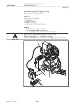
Set nozzle distance
Place burner into service position A [ch. 9.3].
Insert setting gauge and check dimension A (5.0 mm).
If the value measured deviates from dimension A:
Undo screw
1
.
Adjust nozzle body
2
until dimension A is reached.
Re-tighten screw
1
.
A = 5 mm
2
1
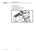
Check basic setting
Dimension S1 can only be checked when the burner is mounted to a boiler door,
which is hinged open.
Hinge open boiler door or if necessary remove mixing head [ch. 9.6].
Turn setting screw
1
until the indicating bolt
2
is flush with the nozzle as-
sembly cover (dimension X = 0 mm).
Check dimension S1 and/or dimension Lx.
Set dimension S1 and/or dimension Lx using setting screw
1
.
Remove plug from indicating bolt
2
.
Turn indicating bolt until it is flush with the nozzle assembly cover
(dimension X = 0 mm).
Replace plug.
Lx = 35
7 mm
X
Lx
S1 = 9 mm
2
1


