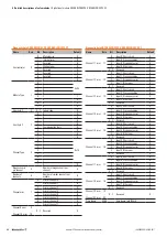
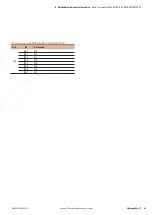

5 Detailed descriptions of safe modules
| Safe power-feed module UR20-PF-O-1DI-SIL
54
1484600000/04/06.2017
u-remote IP20 modules for functional safety manual
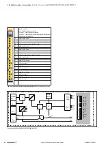
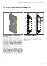
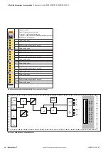
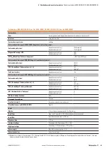
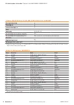
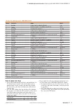
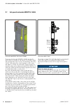
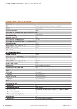
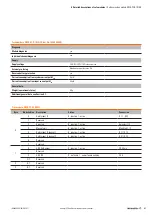
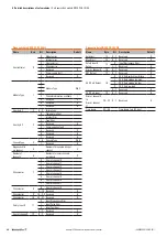
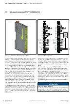
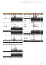
5.7 Safe power-feed module UR20-PF-O-1DI-SIL
Safe power-feed module UR20-PF-O-1DI-SIL (Order No. 1335030000)
The power-feed module UR20-PF-O-1DI-SIL enables the
safe feed-in for the output current path. The module ensures
that an emergency stop circuit can be monitored, and using
the
24 V Safe
output it can be forwarded to a PLC or also
cascaded to a further u-remote station. Almost all Types of
output modules will be safely switched-off (SIL 3/Ple/Cat. 4)
when they are placed within the safety segment (see survey
of switchable modules in section 4.3).
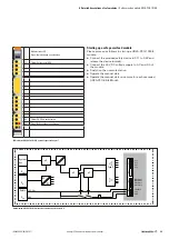
Each time the supply voltage of the module has been
switched on the module has to be initialised manually by
giving a pulse of 0.1 to 2 seconds to the “Man Start” input.
As long as the supply voltage of the module has not been
interrupted the 24 V Safe output path will be reactivated
automatically when the “Autostart” input is used. In case
the “Man Start” input is used there is a pulse needed for the
reactivation.
The evaluation of test pulses in the safety circuits provides
the detection of faults or manipulations of the wiring. There-
fore every second a low pulse of 1 ms is being generated in
each circuit, these pulses are phase-shifted.
The connections Safety Input 0 (S 11, S 21), Man Start 1 and
Autostart 1 are digital inputs Type 3 according to EN 61131-
2. The Man Start 1 input can also be controlled by a standard
PLC output.
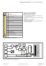
1
3
4
2
1
3
4
2
4
3
1
2
4
3
1
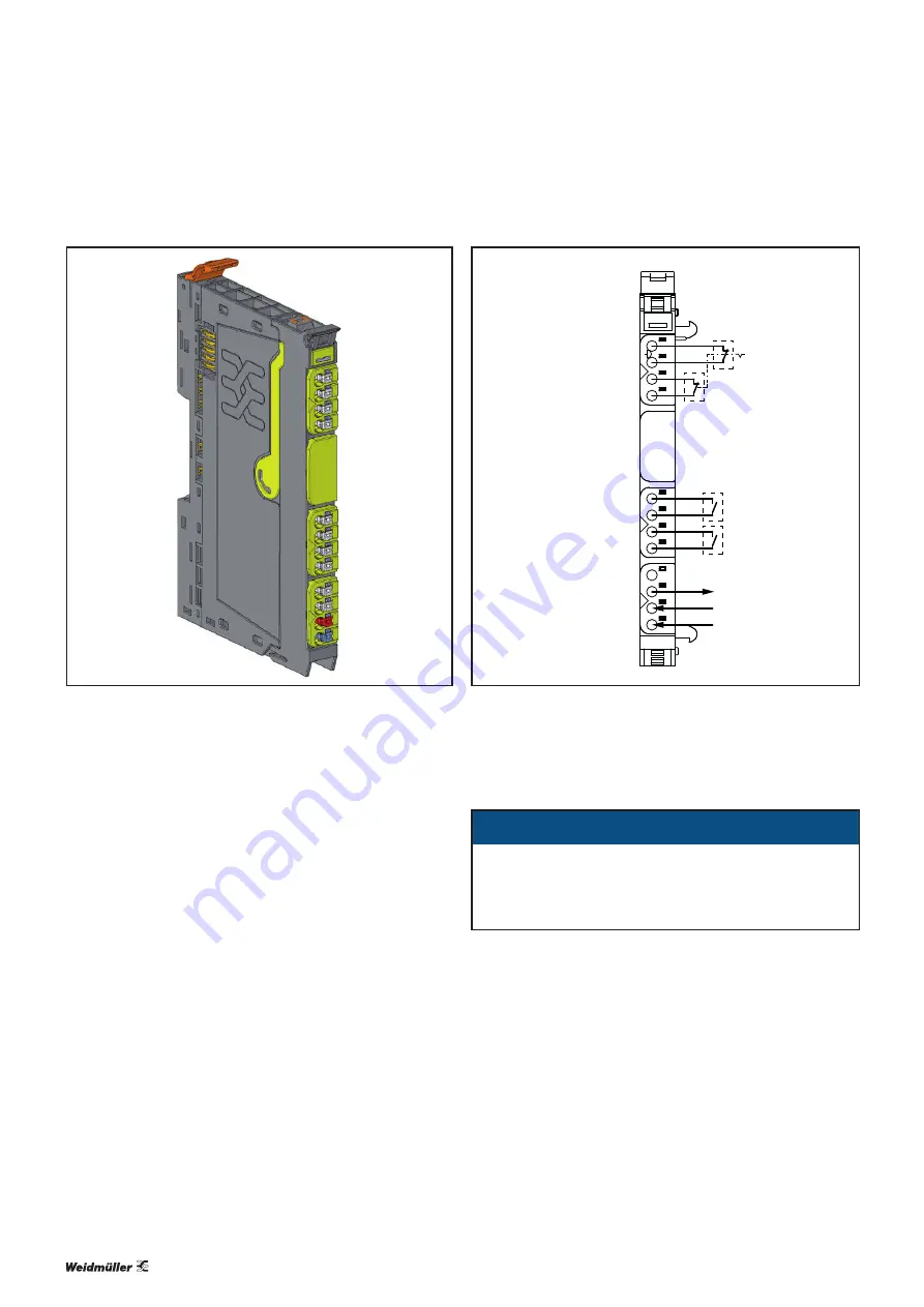
PF-O 1DI
S 11
S 12
S 21
S 22
Man Start 1
or
Man Start 2
Autostart 1
Autostart 2
24 V Safe
24 V
GND
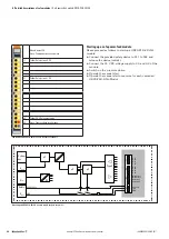
Connection diagram UR20-PF-O-1DI-SIL
The auxiliary outputs S 12, S 22, Man Start 2 and Autostart 2
must only be used for refeeding the allocated inputs.
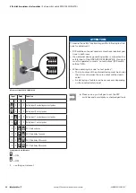
The maximum feed-in current in the output current path is
8 A.
ATTENTION
Risk of material damage!
In the case of a maximum power supply of 8 A and a max-
imum temperature of +60 °C, all wired contacts on the
fourth connector must be connected with 1.5 mm² wiring!
Содержание UR20-4DI-4DO-PN-FSOE
Страница 1: ...Remote I O system u remote IP20 modules for functional safety Manual Original Letʼs connect ...
Страница 8: ...8 1484600000 04 06 2017 u remote IP20 modules for functional safety manual ...
Страница 20: ...20 1484600000 04 06 2017 u remote IP20 modules for functional safety manual ...
Страница 70: ...70 1484600000 04 06 2017 u remote IP20 modules for functional safety manual ...
Страница 72: ...72 1484600000 04 06 2017 u remote IP20 modules for functional safety manual ...
Страница 96: ...96 1484600000 04 06 2017 u remote IP20 modules for functional safety manual ...
Страница 101: ...ANNEX A 5 1484600000 04 06 2017 u remote IP20 modules for functional safety manual EC Declaration of Conformity ...
Страница 102: ...ANNEX A 6 1484600000 04 06 2017 u remote IP20 modules for functional safety manual ...
Страница 103: ...ANNEX A 7 1484600000 04 06 2017 u remote IP20 modules for functional safety manual ...
Страница 104: ...ANNEX A 8 1484600000 04 06 2017 u remote IP20 modules for functional safety manual ...
Страница 105: ...ANNEX A 9 1484600000 04 06 2017 u remote IP20 modules for functional safety manual ...
Страница 106: ...ANNEX A 10 1484600000 04 06 2017 u remote IP20 modules for functional safety manual ...
Страница 107: ...ANNEX A 11 1484600000 04 06 2017 u remote IP20 modules for functional safety manual ...
Страница 108: ...ANNEX A 12 1484600000 04 06 2017 u remote IP20 modules for functional safety manual ...
Страница 109: ...ANNEX A 13 1484600000 04 06 2017 u remote IP20 modules for functional safety manual ...
Страница 110: ...ANNEX A 14 1484600000 04 06 2017 u remote IP20 modules for functional safety manual ...
Страница 111: ...ANNEX A 15 1484600000 04 06 2017 u remote IP20 modules for functional safety manual ...
Страница 112: ...ANNEX A 16 1484600000 04 06 2017 u remote IP20 modules for functional safety manual ...
Страница 113: ...ANNEX A 17 1484600000 04 06 2017 u remote IP20 modules for functional safety manual ...
Страница 114: ...ANNEX A 18 1484600000 04 06 2017 u remote IP20 modules for functional safety manual ...
Страница 115: ...ANNEX A 19 1484600000 04 06 2017 u remote IP20 modules for functional safety manual ...
Страница 116: ...ANNEX A 20 1484600000 04 06 2017 u remote IP20 modules for functional safety manual ...
Страница 117: ...ANNEX A 21 1484600000 04 06 2017 u remote IP20 modules for functional safety manual ...
Страница 118: ...ANNEX A 22 1484600000 04 06 2017 u remote IP20 modules for functional safety manual ...
Страница 119: ...ANNEX A 23 1484600000 04 06 2017 u remote IP20 modules for functional safety manual ...
Страница 120: ...ANNEX A 24 1484600000 04 06 2017 u remote IP20 modules for functional safety manual ...
Страница 121: ...ANNEX A 25 1484600000 04 06 2017 u remote IP20 modules for functional safety manual ...
Страница 122: ...ANNEX A 26 1484600000 04 06 2017 u remote IP20 modules for functional safety manual ...
Страница 124: ...A 28 1484600000 04 06 2017 u remote IP20 modules for functional safety manual ...


