background image

24

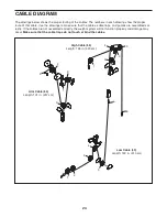
The drawings below shows the proper routing of the cables. The numbers in each drawing show the proper

route of that cable. Use the drawings to make sure that the cables, cable traps, and guards are assembled cor-

rectly. If the cables are not assembled correctly, the weight system will not function properly and damage may

occur.

Make sure that the cable traps do not touch or bind the cables.

1

2

4

2

3

4

5

5

Arm Cable (54)

Length: 101 in. (257 cm)

High Cable (55)

Length: 126 in. (320 cm)

Low Cable (53)

Length: 122 in. (310 cm)

3

1

6

1

2

3

4

5

6

CABLE DIAGRAM

Содержание 6900 831.14922.1

Страница 1: ...manual before using this equipment Keep this manual for future reference Model No 831 14922 1 Serial No Write the serial number in the space above for reference Assembly Operation Maintenance Part List and Drawing Sears Roebuck and Co Hoffman Estates IL 60179 Serial Number Decal under the seat ...

Страница 2: ...RESISTANCE CHART 23 CABLE DIAGRAM 24 MAINTENANCE 25 EXERCISE GUIDELINES 26 PART LIST 29 EXPLODED DRAWING 30 90 DAY FULL WARRANTY Back Cover This drawing shows the location s of the warning decal s If a decal is missing or illegible call 1 877 992 5999 and request a free replacement decal Apply the decal in the location shown Note The decal s may not be shown at actual size ...

Страница 3: ...hoes for foot protec tion 10 Keep hands and feet away from moving parts 11 Always secure the weight stack with the lock pin and the lock after exercising to prevent unauthorized use of the weight system see LOCKING THE WEIGHT STACK on page 23 12 Make sure that the cables remain on the pul leys at all times If the cables bind while you are exercising stop immediately and make sure that the cables a...

Страница 4: ...cular system the weight system will help you to achieve the specific results you want For your benefit read this manual carefully before using the weight system If you have questions after reading this manual please see the front cover of this manual To help us assist you note the product model number and serial number before contacting us The model number and the location of the serial number dec...

Страница 5: ...arriage Bolt 67 M10 x 25mm Button Screw 77 M10 x 130mm Bolt 72 M10 x 25mm Bolt 74 M10 x 64mm Bolt Set 76 M10 x 63mm Bolt 75 11mm Spacer 86 13mm Spacer 52 M12 Nut 84 PART IDENTIFICATION CHART Refer to the drawings below to identify small parts used in assembly The number in parentheses by each draw ing is the key number of the part from the PART LIST near the end of this manual IMPORTANT If you can...

Страница 6: ...structions Assembly requires two persons Because of its weight and size assemble the weight system in the location where it will be used Make sure that there is enough clearance to walk around the weight system Place all parts in a cleared area and remove the packing materials Do not dispose of the packing materials until assembly is completed For help identifying small parts use the PART IDENTIFI...

Страница 7: ...the Foot Plate must pivot easily Frame Assembly 1 1 38 2 Attach the Weight Guides 21 and the Base 1 to the Stabilizer 2 with two M10 x 67mm Bolts 71 two M10 Washers 57 and two M10 Locknuts 56 Do not tighten the Locknuts yet 2 56 71 71 2 57 57 21 56 72 To make assembly easier read the information on page 6 before you begin 1 ...

Страница 8: ... two M8 x 63mm Carriage Bolts 87 and two M8 Locknuts 58 Do not tighten the Locknuts yet 3 4 7 58 58 3 Attach the Upright 3 to the Base 1 with two M8 x 63mm Carriage Bolts 87 and two M8 Locknuts 58 Do not tighten the Locknuts yet 87 58 1 58 87 3 1 ...

Страница 9: ...pin on the Weight Selector is oriented as shown Apply some of the included grease inside the indicated holes in the remaining Weight 22 Then slide the Weight onto the Weight Guides 21 5 6 21 5 Attach the Seat Tube 6 to the Upright 3 with two M8 x 65mm Bolts 68 two M8 Washers 59 and two M8 Locknuts 58 Do not tighten the Locknuts yet Attach the Seat Tube 6 to the Front Leg 7 in the same way 7 6 3 58...

Страница 10: ...10 x 64mm Bolt Set 76 Make sure that the barrel of the Bolt Set is inserted through both sides of the bracket on the Front Leg 8 9 7 Attach the Top Frame 4 to the Upright 3 with two M10 x 67mm Bolts 71 two M10 Washers 57 and two M10 Locknuts 56 Do not tighten the Locknuts yet Attach the Top Frame 4 to the Weight Guides 21 with two M10 x 25mm Bolts 74 Do not tighten the Bolts yet See steps 2 to 7 T...

Страница 11: ...into the indicated holes in the Upright 3 5 69 69 40 40 12 11 10 39 57 77 66 56 9 42 Grease 12 Apply grease to an M10 x 51mm Bolt 66 Attach a Cable Pivot 39 to the Left Arm 10 with the M10 x 51mm Bolt 66 and an M10 Locknut 56 Do not overtighten the Locknut the Cable Pivot must pivot easily Wet the inside of a Large Foam Pad 42 with soapy water Slide the Large Foam Pad onto the Left Arm 10 Attach a...

Страница 12: ...o not overtighten the Locknut the Left Arm must pivot easily Attach the Right Arm 9 to the Pivot Frame 5 in the same way 10 9 44 56 67 57 20 5 44 Grease Grease 14 See the CABLE DIAGRAM on page 24 to identify the cables as you assemble them Identify the Arm Cable 54 Apply grease to an M8 x 22mm Shoulder Bolt 65 Attach the Arm Cable 54 to the left Cable Pivot 39 with the M8 x 22mm Shoulder Bolt 65 a...

Страница 13: ... 54 41 15 16 Route the Arm Cable 54 around a Thick Pulley 48 Attach the Thick Pulley 48 and two Half Guards 43 to the Double U bracket 63 with an M10 x 46mm Bolt 81 and an M10 Locknut 56 Make sure that the Half Guards are on the outside of the Double U bracket as shown 48 43 43 63 56 54 16 17 56 3 57 46 50 75 54 41 81 41 17 Route the Arm Cable 54 over a V pulley 46 Attach the V pulley 46 a Large C...

Страница 14: ...hrough the Leg Lever 8 and the Front Leg 7 Attach a Thick Pulley 48 inside the Leg Lever 8 above the Low Cable 53 with an M10 x 67mm Bolt 71 two M10 Washers 57 two 13mm Spacers 52 and an M10 Locknut 56 20 Attach a Thick Pulley 48 inside the Front Leg 7 above the Low Cable 53 with an M10 x 67mm Bolt 71 two M10 Washers 57 two 13mm Spacers 52 and an M10 Locknut 56 19 8 7 53 52 52 57 57 48 71 56 20 56...

Страница 15: ...uards 43 to the Double U bracket 63 with an M10 x 46mm Bolt 81 and an M10 Locknut 56 Make sure that the Half Guards are on the outside of the Double U bracket as shown 21 56 22 48 81 81 3 23 Route the Low Cable 53 under a Thick Pulley 48 Attach the Thick Pulley 48 and two Half Guards 43 to the Base 1 with an M10 x 46mm Bolt 81 and an M10 Locknut 56 Make sure that the Half Guards are on the outside...

Страница 16: ...ch the Thin Pulley 47 inside the Top Frame 4 with an M10 x 67mm Bolt 71 an M10 Washer 57 and an 11mm Spacer 86 Make sure that the Thin Pulley does not fall out of the Top Frame while you complete steps 27 and 28 24 Attach the Low Cable 53 to the U bracket 45 with an M8 Washer 59 and an M8 Locknut 58 See the inset drawing Do not overtighten the M8 Locknut 58 it should be threaded onto the end of th...

Страница 17: ... outside of the U bracket 45 29 Route the High Cable 55 over a Thick Pulley 48 and downward through the Top Frame 4 Attach the Thick Pulley 48 inside the Top Frame 4 with an M10 x 67mm Bolt 71 two M10 Washers 57 two 13mm Spacers 52 and an M10 Locknut 56 28 Route the High Cable 55 upward through the Top Frame 4 and over a Thin Pulley 47 Attach the Thin Pulley 47 inside the Top Frame 4 with the M10 ...

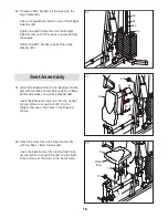
Страница 18: ... 16 to the Backrest Frame 61 with two M6 x 16mm Screws 62 an M6 x 32mm Screw 64 and an M6 Washer 82 Insert the Backrest Frame 61 into the Upright 3 and tighten a Long Knob 91 into the Upright and one of the holes in the Backrest Frame 32 Attach the Seat 15 to the Seat Frame 73 with four M6 x 16mm Screws 62 Insert the Seat Frame 73 into the Seat Tube 6 and tighten a Long Knob 91 into the Seat Tube ...

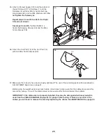
Страница 19: ...e Left Shroud 17 and the Shroud Support 19 with two M4 x 12mm Screws 78 and two M4 Washers 33 Do not tighten the Screws yet 33 Insert the Pad Tube 29 into the Front Leg 7 Slide a Small Foam Pad 28 onto each side of the Pad Tube 29 Then press a Pad Cap 34 into each Small Foam Pad Slide a Small Foam Pad 28 onto each end of the Leg Lever 8 Then press a Pad Cap 34 into each Small Foam Pad 33 34 29 7 8...

Страница 20: ... not properly installed they may be damaged when heavy weight is used See the CABLE DIAGRAM on page 24 for proper cable routing If there is any slack in the cables you will need to remove the slack by tightening the cables See MAINTENANCE on page 25 36 14 13 62 35 Attach a Shroud Support 19 and the bottom of the Left Shroud 17 to the Base 1 and the Stabilizer 2 with four M4 2 x 16mm Self tap ping ...

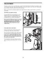
Страница 21: ...stack Turn the bent end downward Note Due to the cables and pulleys the amount of resistance at each exercise station may vary from the weight setting Use the WEIGHT RESISTANCE CHART on page 23 to find the approximate amount of resistance at each weight station 37 26 22 83 ATTACHING THE ACCESSORIES Attach the Lat Bar 35 to the High Cable 55 at the high pulley station with a Cable Clip 37 For some ...

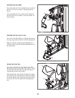
Страница 22: ...t Leg 7 Insert the Curl Post 13 into the Front Leg and secure it in place with the Short Knob 25 When performing an exercise that does not require the Curl Pad 14 remove the Curl Pad and replace the 50mm Round Inner Cap 30 into the Front Leg 7 Store the Curl Pad away from the weight sys tem 25 9 10 14 CONVERTING THE FOOT PLATE To use the Foot Plate 38 as a footrest while using the low pulley stati...

Страница 23: ... below shows the approximate weight resistance at each exercise station The numbers in the left col umn refer to the 12 5 lb weights Note The weight resistance shown for the butterfly arm station is for each arm The actual resistance at each station may vary due to differences in individual weights as well as friction between the cables pulleys and weight guides 21 88 LOCKING THE WEIGHT STACK To l...

Страница 24: ...s cable traps and guards are assembled cor rectly If the cables are not assembled correctly the weight system will not function properly and damage may occur Make sure that the cable traps do not touch or bind the cables 1 2 4 2 3 4 5 5 Arm Cable 54 Length 101 in 257 cm High Cable 55 Length 126 in 320 cm Low Cable 53 Length 122 in 310 cm 3 1 6 1 2 3 4 5 6 CABLE DIAGRAM ...

Страница 25: ...he M10 Locknut 56 and the M10 x 51mm Bolt 66 from the two Half Guards 43 the U bracket 45 the Small Cable Trap 51 and the Thick Pulley 48 Reattach the Thick Pulley 48 Small Cable Trap 51 and Half Guards 43 to the other hole in the U bracket 45 Make sure that the Small Cable Trap is in the proper position and that the Low Cable 53 and the Thick Pulley move smoothly Loosen the M12 Nut 84 on the High...

Страница 26: ...S Familiarize yourself with the equipment and learn the proper form for each exercise Use your own judgment to determine the appropriate length of time for each workout and the numbers of repetitions and sets to complete Progress at your own pace and be sensitive to your bodyʼs signals Follow each workout with at least one day of rest Warming Up Start with 5 to 10 minutes of stretching and light e...

Страница 27: ...and enjoyable part of your life Exercise Lbs Sets Reps Exercise Lbs Sets Reps 1 6 2 7 3 8 4 9 5 10 Exercise Time Distance Speed Strength Date Exercise Lbs Sets Reps Exercise Lbs Sets Reps 1 6 2 7 3 8 4 9 5 10 Exercise Lbs Sets Reps Exercise Lbs Sets Reps 1 6 2 7 3 8 4 9 5 10 Strength Date Strength Date Aerobic Date Exercise Time Distance Speed Aerobic Date Exercise Time Distance Speed Aerobic Date...

Страница 28: ...28 NOTES ...

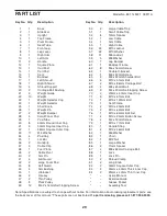
Страница 29: ... 1 Arm Cable 55 1 High Cable 56 22 M10 Locknut 57 22 M10 Washer 58 11 M8 Locknut 59 5 M8 Washer 60 1 Leg Bumper 61 1 Backrest Frame 62 8 M6 x 16mm Screw 63 1 Double U bracket 64 1 M6 x 32mm Screw 65 2 M8 x 22mm Shoulder Bolt 66 3 M10 x 51mm Bolt 67 2 M10 x 86mm Carriage Bolt 68 4 M8 x 65mm Bolt 69 3 M4 x 20mm Self tapping Screw 70 2 20mm x 40mm Inner Cap 71 9 M10 x 67mm Bolt 72 1 M10 x 130mm Bolt ...

Страница 30: ... 30 77 13 14 62 36 35 36 37 6 62 62 68 68 68 68 28 29 28 30 52 57 56 52 48 57 30 71 34 28 53 28 56 31 87 87 81 43 43 56 48 71 71 8 34 9 10 40 57 57 83 80 57 30 38 15 57 34 34 20 42 69 73 58 59 72 25 58 58 30 33 76 76 69 57 56 52 48 52 71 60 57 7 91 94 94 93 EXPLODED DRAWING A Model No 831 14922 1 R0911A ...

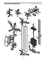
Страница 31: ... 43 48 56 51 58 59 45 49 56 56 81 43 48 43 48 43 43 63 81 88 89 90 90 91 74 19 49 33 33 19 49 33 33 32 56 56 41 57 46 50 41 75 41 57 46 50 41 75 62 61 58 59 56 64 81 58 58 48 12 3 56 57 71 56 57 86 86 57 71 56 57 52 52 57 17 18 16 78 33 78 33 49 33 33 82 93 70 70 EXPLODED DRAWING B Model No 831 14922 1 R0911A ...

Страница 32: ...m To purchase a protection agreement U S A or maintenance agreement Canada on a product serviced by Sears 1 800 827 6655 U S A 1 800 361 6665 Canada Para pedir servicio de reparación a domicilio y para ordenar piezas 1 888 SU HOGAR 1 888 784 6427 Get it fixed at your home or ours Registered Trademark TM Trademark SM Service Mark of Sears Brands LLC Marca Registrada TM Marca de Fábrica SM Marca de ...

Отзывы: