


Installation
43
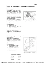
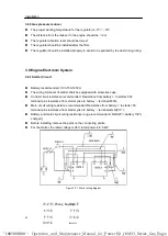
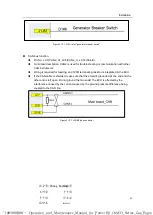
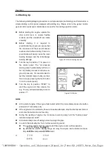
3.9.2 Charging Circuit
The charging cable shall be a
complete cable without intermediate
connector;
Terminals of B+/D+/W shall be
provided with protective caps;
Permissible voltage decrease on
charge cable
≤
1V;
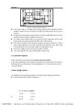
The schematic diagram of the alternator
wiring is as follows:
Figure 3.9.2 - Alternator wiring diagram
3.10 Engine Electronic Controlling System
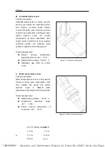
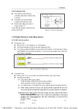
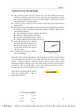
3.10.1 ECU wire connection
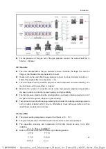
"ECU power" wire
ECU pin No.: J1-121 (positive), J1-123 (negative)
Functional description: ECU main power supply (24V DC)
The red wire marked POWER+ is connected to the "". The black wire marked
with POWER- is connected to the "battery-". The cross-sectional area of the wires is at
least 2.5mm
2
separately.
Figure 3.10.1 A-Wire for "ECU power"
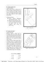
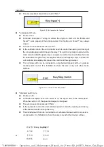
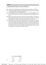
"key switch" wire
ECU pin No.: J1-12. Connect the wire with the "" with a key switch.
Functional description:
The switch is ECU power switch.
When the switch is ON, ECU will in working condition.
When the switch is OFF, the engine will be stopped.
Any interference on this switch from other electrical devices should be avoided.
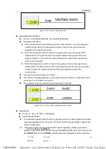
When the key switch is turned on, the engine will have a self-test time of 2-5S.
It is recommended to start the engine after the engine self-test is completed.
When the T15 switch is OFF to stop the engine, the main switch of the battery
shall be maintained for at least 2 min, so that the relevant data of the engine
working cycle (fuel consumption and other information) is written into the
memory of ECU.
于千钧
“1005098300 - Operation_and_Maintenance_Manual_for_PowerKit_16M33_Series_Gas_Engine, A”
林世龙
许太法
宋安泽
20200425
于千钧
张安勇/Zhang Anyong
王巧荣


