background image

38

6

36

18

18

5

4

3

26

2

1

27

27

13

55

12

19

19

17

14

17

29

30

63

63 62

22

64

28

10

61

25

31

37

50

49

48

59

34

34

52

35

53

32

37

7

19

19

40

40

37

57

20

56

57

20

LRV-B_Deck_4_r1

RIDING MOWER 

MODEL NUMBER WELRVBA (96026000100)

MOWER DECK


PRODUCT NUMBER 960 26 00-01

7

Your new riding mower has been assembled at the factory with the exception of those parts 

left unassembled for shipping purposes. To ensure safe and proper operation of your riding 

mower all parts and hardware you as sem ble must be tightened securely. Use the correct 

tools as nec es sary to ensure proper tightness. 

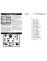
TOOLS REQUIRED FOR ASSEMBLY

A socket wrench set will make assembly 

easier.  Stan dard wrench sizes you need 

are listed below.       
(1)  1/2" wrench 

(1)  Utility knife

(1)  Tire  pressure  gauge
When right or left hand is mentioned in 

this man ual, it means when you are in the 

operating po si tion (seated be hind the steer-

 ing wheel).

TO REMOVE RIDING MOWER FROM 

CARTON

UNPACK CARTON

1.  Remove all accessible loose parts and 

parts boxes from carton.

2.   Cut along dotted lines on all four panels 

of carton. Remove end panels and lay 

side panels flat.

3.  Remove packing materials from riding 

mower.

4.  Check for any additional loose parts or 

cartons and remove.

NOTE:


Only cut carton with a short blade 

utility knife, a long blade or saw can puncture 

tires on unit.

ASSEMBLY/PRE-OPERATION

TO INSTALL STEERING WHEEL 

1.  Slide extension shaft onto steering shaft.

2.  Slide steering shaft protective foam cover 

over steering shaft.

3.  Place steering boot over steering shaft 

and push down to secure.

4.  Position front wheels of the riding mower 

so they are pointing straight forward.

5.  Remove steering wheel adapter from 

steering wheel and slide adapter onto 

steering shaft.

7.  Press steering wheel into position on 

shaft, install large washer, lock washer, 

bolt and tighten securely.

8.  Snap steering wheel insert into center of 

steering wheel securely.

Foam Cover

Adapter

Steering Wheel

Insert

Washer

Lock Washer

Bolt

Steering Shaft

Steering Boot

Extension 

Shaft

HOW TO SET UP YOUR RIDING 

MOWER

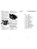
CHECK BATTERY

Ensure battery is securely fastened, and that 

all wires are securely connected.

•  Battery is located under the seat.

•  Battery has been fully charged from the 

factory, before installation.

Seat

Battery

Содержание 96026000100

Страница 1: ...ervice through its authorized distributors and dealers therefore all requests for parts and service should be directed to your local dealer s The philosophy of HOP is to continually improve all of its...

Страница 2: ...Battery must be maintained in accordance with the instructions furnished 4 The Warranty does not apply to any products used for rental or commercial purposes 5 This Warranty applies only to products w...

Страница 3: ...e machine only in daylight or good artificial light Do not operate the machine while under the influence of alcohol or drugs Watch for traffic when operating near or crossing roadways Use extra care w...

Страница 4: ...the operator Be alert and turn machine off if a child enters the area Beforeandwhilebacking lookbehindand down for small children Never carry children even with the blade shut off They may fall off an...

Страница 5: ...hing immediately Never overfill fuel tank Replace gas cap and tighten securely GENERAL SERVICE Never operate machine in a closed area Keep all nuts and bolts tight to be sure the equipment is in safe...

Страница 6: ...u experience any problem you cannot easily remedy please contact a qualifiedservicecenter Wehavecompetent well trained representatives and the proper tools to service or repair this riding mower Pleas...

Страница 7: ...ong dotted lines on all four panels of carton Remove end panels and lay side panels flat 3 Remove packing materials from riding mower 4 Check for any additional loose parts or cartons and remove NOTE...

Страница 8: ...djustment handle Bolt Flat washer Seat pan Pad Tape Slot Tab LUMBAR SUPPORT Loosen lumbar adjustment knob Slide seat back up or down to most com fortable position for lower back support Tighten lumbar...

Страница 9: ...h to assure that you receive the best performanceandsatisfactionfromthisQual ity Product Please review the following checklist All assembly instructions have been completed No remaining loose parts in...

Страница 10: ...LOCK TENSION CHAIN 33 532 43 61 50 SPRING ADJUSTER TENSION 34 877 10 10 40 PIN CLEVIS 5 16 X 2 1 2 36 532 43 57 22 SHAFT INPUT CLUTCH 37 532 43 61 52 SPROCKETSPLINED14TOOTH 39 532 43 04 70 BEARING BAL...

Страница 11: ...ts Save this manual for future reference Our riding mowers conform to the applicable safety standards of the American National Standards Institute DECK CLUTCH LEVER Used to engage the mower blade BRAK...

Страница 12: ...T REST 16 532 43 94 01 PANEL ASM CONTROL 18 ENGINE 215807 1529 G1 439273 NON CALIFORNIA ORDER PARTS FROM ENGINE MANUFACTURER 19 532 43 68 61 KEEPER BELT 22 532 44 21 30 DECK CLUTCH ASM 23 532 14 98 46...

Страница 13: ...f grass and types of grass being mowed TO OPERATE MOWER Your riding mower is equipped with an operator presence sensing switch Any attempt by the operator to leave the seat with the engine running and...

Страница 14: ...Deflector Shield Hinge Bracket TO TRANSPORT When pushing or towing your riding mower besuretodisengagetransmissionbyplacing shifter in neutral Raisemowerheightadjustmenttoitshigh estpositionwithmowerh...

Страница 15: ...necessary add oil until FULL mark on dipstick is reached Do not overfill For cold weather operation you should change oil for easier starting See the oil viscositychartintheMaintenancesection of this...

Страница 16: ...re mowing Regulategroundspeedbyselectingalow enough gear to give the mower cutting performance as well as the quality of cut desired When operating attachments select a groundspeedthatwillsuittheterra...

Страница 17: ...sureproper air fuel mixture and help your engine run better and last longer BEFORE EACH USE 1 Check engine oil level 2 Check brake operation 3 Check tire pressure 4 Check operator presence and ROS sys...

Страница 18: ...your hands with gloves and or wrap blade with heavy cloth 2 Remove blade bolt by turning counter clockwise 3 Install new blade with stamped THIS SIDE UP facing deck and mandrel as sembly IMPORTANT To...

Страница 19: ...priate section in manual unless directed to service center 19 BATTERY Your riding mower has a battery charging system which is sufficient for normal use Keep battery and connectors clean Only recharge...

Страница 20: ...is to be stored for a period of time clean it thoroughly remove all dirt grease leaves etc Storeinaclean dryarea 1 Cleanentireridingmower See CLEAN ING in the Maintenance section of this manual 2 Ins...

Страница 21: ...TERY CAUTION Lead acid batteries gener ate explosive gases Keep sparks flame and smoking materials away from batteries Always wear eye protection when around batteries If your battery is too weak to s...

Страница 22: ...tions in the INSTALL STEERING COLUMN section of this manual TO REMOVE WHEEL FOR REPAIRS FRONT WHEEL 1 Block up front axle securely 2 Remove dust cover retaining ring and washer to allow wheel removal...

Отзывы: