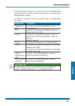
WEBTEC HPM7000 Скачать руководство пользователя страница 491

ESP

AÑOL

491

La medición comienza después de que se activan uno o dos disparadores 
definidos.
La medición se detiene después de que se activan uno o dos disparadores 
definidos o se presiona el botón 

Iniciar/Detener.

Fig. 36 

Lógica del disparador, ajustes

Funcionamiento

Содержание HPM7000

Страница 1: ...HPM7000 Datalogger Operating Manual Bedienungsanleitung Manuel d utilisation Manual de instrucciones...

Страница 2: ......

Страница 3: ...arnings 14 2 3 Safety Related Warnings 16 2 4 Technical Personnel 17 3 Design and Function 18 3 1 Overview 19 3 2 Functions and Features 20 3 3 Connections 21 3 3 1 Webtec CAN External CAN 22 3 3 2 D...

Страница 4: ...8 6 1 1 Operating the Device 39 6 2 Screen Design 42 6 2 1 Status Bar 43 6 2 2 Quick Start Menu 44 6 2 3 Screen Keyboards 46 6 2 4 Menu Area 48 6 2 5 Options 50 6 2 6 Resetting Values 51 6 3 Measureme...

Страница 5: ...7 Project Management 82 6 7 1 SPC Service Project Container 82 6 7 2 Creating an SPC Service Project Container 84 6 8 Menu 87 6 9 File Manager 88 6 9 1 Managing Files 89 6 10 Sensors 90 6 10 1 CAN X 9...

Страница 6: ...ce 117 7 2 Resetting the Device to its Default Settings 118 7 3 Updating the Firmware 120 8 Packaging and Transporting 122 9 Cleaning and Maintenance 123 9 1 Cleaning 123 9 2 Maintenance 123 9 3 Repai...

Страница 7: ...5 3 LAN 129 11 6 Analog Input Modules HPM7000 IM ANO HPM7000 IM ANI 130 11 6 1 Connections SR Sensors 130 11 6 2 Connection External Sensor 130 11 7 CAN Input Module HPM7000 IM CAN 131 12 Appendix 13...

Страница 8: ...steps described Pay particular attention to Chapter Safety Information and follow the instructions Notation and Symbols INFORMATION This information symbol indicates useful tips which is provided Thi...

Страница 9: ...ut sensor detection can be used with analog signals as well as a digital input output and two frequency channels The HPM7000 can be extended by two input modules providing additional connections and f...

Страница 10: ...les water in oil volumes and output for example The device is exclusively designed for commercial use in mobile and stationary systems 1 2 Improper Use All usage and conditions of use which are contra...

Страница 11: ...standard related documents specified in the Dec laration of Conformity 1 4 Equipment Supplied Check the parts included in the supply package prior to starting up the device If anything is missing plea...

Страница 12: ...the art technology with regard to accuracy principles of operation and safe operation of the equipment 2 1 Notation This section explains how the various types of safety information are presented wit...

Страница 13: ...sures to avoid the risk WARNING Type and source of the risk Consequences of failure to observe the warning Measures to avoid the risk CAUTION Type and source of the risk Consequences of failure to obs...

Страница 14: ...radio frequency ener gy Risk of fatal or severe personal injury Medical devices are sensitive to radio frequency energy The functionality of pacemakers other medical implants and hearing aids can be i...

Страница 15: ...as to whether interference or risks could result from its use IMPORTANT Risk of property damage The device must be connected and put into operation by proper ly trained technical personnel Avoid usin...

Страница 16: ...fety Related Warnings Throughout this operating manual warnings which relate to specific individual functional processes or activities are provided directly preceding the corresponding instructions Sa...

Страница 17: ...ersonnel entrusted with starting up and operating the device must produce evidence of the necessary qualification Qualification can be obtained through participation in a relevant training course or r...

Страница 18: ...formation on the design of the device and the functions provided The connection ports pin assignments and interfaces available on the device are described INFORMATION Information on the input modules...

Страница 19: ...ts power connection CAN X CAN Y D IN D OUT F1 F2 2 Input module A option 3 Input module B option 4 Communication ports 2 USB Host 1 USB Device LAN 5 On Off key enable or disable touch or display 6 Con...

Страница 20: ...g of pressure temperature volume flows frequencies speeds particles water in oil volumes and output For recording saving and analyzing measured data Various types of measurement and their representati...

Страница 21: ...bus sensors 4 D IN D OUT F1 F2 To connect sensors 5 USB port device To connect a PC 6 USB port Host 1 To connect a mass storage device 7 USB port Host 2 To connect a mass storage device 8 LAN connecti...

Страница 22: ...to 24 Webtec sensors max 24 channels with automatic sensor detection Webtec CAN 4 3 5 2 1 Fig 4 Connection port CAN X CAN Y PIN Designation 1 Shielding 2 Ub 24 VDC 3 GND 4 CAN High 5 CAN Low INFORMATI...

Страница 23: ...rameterization of the connection ports is available in Chapter Sensors INFORMATION It is not possible to mix operation on one CAN bus using sensors with automatic sensor detection Webtec CAN and exter...

Страница 24: ...e frequency inputs are also suitable for the connection of volume flow sensors Information on switching the connection is available in Chapter Sensors Refer to the following overview for the PIN assig...

Страница 25: ...es the slots for the input modules 2 1 Fig 6 Connection port input module Pos Designation Description 1 Input module SLOT A First slot for an input module 2 Input module SLOT B Second slot for an inpu...

Страница 26: ...ENGLISH 26 4 Input Modules This chapter provides information on the input modules available INFORMATION The input modules can be obtained separately To do this contact your sales outlet Input Modules...

Страница 27: ...ed or exchanged while the device is in operation hot plug or hot swap 1 Loosen the two screws 1 in the dummy cover of the slot e g input module A on the top of the device 2 Remove the dummy cover from...

Страница 28: ...connectioncanbeusedtocompletefastmeasurements The Analog Input Module HPM7000 IM ANI is galvanically isolated from the device The figure indicates the connection ports on the analog input module 1 2 3...

Страница 29: ...automatic sensor detection can also be connected to one of the analog connections IN1 IN3 via an adapter current voltage converter INFORMATION Further information on connecting sensors without sensor...

Страница 30: ...ng resistors The passive CAN bus connections are optimally suited to reading out diesel motor data via the SAE J1939 protocol Messages from oth er CAN protocols can also be read out In this case the C...

Страница 31: ...0 IM CAN PIN Designation 1 Shielding 2 Not connected 3 GND 4 CAN High 5 CAN Low After connecting the sensors without sensor detection complete the necessary settings for the electrical connection and...

Страница 32: ...er HPM7000 AC PSU supplied to charge the battery Avoid fully charging or total discharge of the battery to increase the service life of the battery The optimum battery charge is be tween 10 and 90 Onl...

Страница 33: ...the firmware version and serial number are displayed Switching the Device Off 1 When switched on press and hold the On Off key for at least 5 seconds The device is switched off Alternatively 1 When sw...

Страница 34: ...Connect the sensors to a bus cable or a Y junction refer to figure 3 Connect a bus cable to the corresponding port on the device which is switched on IMPORTANT The device does not record data from se...

Страница 35: ...ce and use the fold out stand to improve visibility The stand can be folded out to a maximum angle of 40 Fig 13 Using the fold out stand 1 Pull the fold out stand on the rear side of the device to the...

Страница 36: ...NGLISH 36 5 5 Mounting the Device If necessary you can mount the device on a wall after assembling the VESA holder 100 mm 100 mm on the rear panel of the device Fig 14 Assembling the holder Starting U...

Страница 37: ...ual supplied with the VESA holder 2 Mount the device on the VESA holder 3 Screw the device using four retaining screws and an appropriate tool The device is mounted INFORMATION The maximum screw in de...

Страница 38: ...vice 6 1 Basic Factors The device is immediately ready for use after being started up The sensors connected are normally displayed in the list view Select one of the four display options for the measu...

Страница 39: ...movements and their functions Finger move ments Function Tap your finger on the respective button or ele ment to initiate a function Swipe your finger through lists and views to scroll Draw two finge...

Страница 40: ...ey is used to start and stop measurements and four function keys are assigned context sensitive functions The four context sensitive function keys are used to initiate the functions according to the c...

Страница 41: ...fingers directly on the buttons displayed on the screen to navigate through the device s menus and select the respective functions A screen keyboard appears with which to enter digits and characters...

Страница 42: ...tatus bar Display for system status 2 Button Projects Tem plates To select projects or templates 3 Main view Display of the current function 4 Button Quick Start Menu To open the Quick Start menu 5 Me...

Страница 43: ...and time The table below indicates the possible symbols Symbol Function Connection of a device at the USB1 connection port Connection of a device at the USB2 connection port Number of active channels...

Страница 44: ...Fig 16 Quick Start menu The following information is displayed Memory utilization internal device memory Memory utilization USB 1 Memory utilization USB 2 Memory locations which are not configured ar...

Страница 45: ...ipe from the top screen edge downwards The Quick Start menu opens 2 Swipe upwards over the QuickStart menu The Quick Start menu closes INFORMATION Open the Settings menu by tapping on the gearwheel sy...

Страница 46: ...t field The following keyboard is available to enter texts and digits Fig 17 Screen keyboard characters and digits INFORMATION The keyboard layout varies according to various languages and can be chan...

Страница 47: ...7 Fig 18 Screen keyboard simple arithmetic operations The following keyboard is available to complete more advanced mathematical calculations Fig 19 Screen keyboard advanced mathematical calculations...

Страница 48: ...ensitive function keys on the device Not all the functions are always available The table below indicates the possible buttons Symbol Function Switch to the main view Switch between measurement views...

Страница 49: ...Add an entry Edit a setting Record a measuring point Keystroke presetting Confirm current selection or adapted settings Discard current selection or adapted settings Zoom in on current view Zoom out f...

Страница 50: ...ignation Description Edit channels Define settings for the channels Save Template as Save the current measurement view as a tem plate Reset Reset values Information Unhide Hide information on the sens...

Страница 51: ...iption Delta to zero Reset delta to zero Channel to zero Reset the channel offset to zero to max 2 FS D IN to zero Reset the D IN counter to zero D OUT to zero Reset the D OUT output to zero MIN MAX R...

Страница 52: ...and adjust them as necessary Further information on adjusting channels is available in Chapter Edit Channels Changing the Measurement View You can switch between the individual measurement views 1 Ta...

Страница 53: ...by the device according to the connec tions used e g CANY 1 24 CANX 1 24 2 Names of the active channels 3 Current measured values of the channels 4 Switch to the previous screen display combination 5...

Страница 54: ...and their current measured values This view enables you to follow twelve channels in one view If more than twelve channels are active you can scroll through the list 1 2 Fig 23 List 12 view Pos Descr...

Страница 55: ...5 7 8 8 Fig 24 Manometer view Pos Description 1 Designation of the active channel 2 Name of the active channel 3 Maximum measured value 4 Minimum measured value 5 Starting value for measuring range 6...

Страница 56: ...w displays the current measured values INFORMATION You can save the measurements in order to analyze the measured values using curve tools 1 2 3 4 Fig 25 Trend graph view Pos Description 1 Name of the...

Страница 57: ...s 1 Tap on any channel 2 Swipe to the right or left The list of channels displayed is scrolled through Scaling the Axes When using the trend graph view you can use the Curve tools button to adjust the...

Страница 58: ...he size of the graph 1 Tap with two fingers on the screen and drag the fingers apart The graph is enlarged 2 Tap with two fingers on the screen and drag the fingers towards each other The graph is red...

Страница 59: ...l 2 Selected channel increased line thickness 3 Current measured value of the channel 4 Cursor B of the selected channel 5 Trend graph line of the selected channel 6 Cursor A of the selected channel I...

Страница 60: ...Fig 28 Curve tools 2 Tap on the button The options are displayed 3 Tap on the Curve tools button The functions available are displayed Designation Description Jump to MIN The cursor springs to the min...

Страница 61: ...ator for the X axis 6 Delta indicator for the Y axis displayed per channel The following statuses can be configured Status Description Cursor is hidden Cursor is unhidden and active You can move the a...

Страница 62: ...to edit the channels in the measurement views The functions can be used to hide or activate deactivate individual channels 1 Tap on the button 2 Tap on the Edit channels button The window in which to...

Страница 63: ...numbers or manual movement 7 Edit further channel settings 3 Tap on the button for the channel to be edited The window in which to edit the channel selected opens INFORMATION Alternatively tap on the...

Страница 64: ...u can define the number of decimal places the unit and the minimum and maximum alarm and warning values for each channel If a channel reaches a defined alarm or warning value the current measured valu...

Страница 65: ...is waiting for the defined trigger to be triggered in order to record the mea sured data Measurement is started and measured data is recorded 1 Tap on the Start Stop button The measurement starts up I...

Страница 66: ...ce s working memory and stored in a defined device memory The ACT values or ACT MIN and MAX values are stored depending on the measuring method and settings selected You can switch between the measuri...

Страница 67: ...ured value the Min and Max values are also saved The measurement is completed independent of the current storage rate at a scanning rate of 1 ms If the predefined memory area is full the data compress...

Страница 68: ...parameters 2 Define the values according to your application The following settings are available to be defined Designation Description Storage interval Set the storage interval of the measurement in...

Страница 69: ...ENGLISH 69 Fig 32 Data logger settings The file size expected and maximum storage time for the measurement are calculated and displayed according to the applicable defined parameters Operation...

Страница 70: ...ding button D IN falling slope Recording of a measuring point on transition of a digital signal from High to Low D IN rising slope Recording of a measuring point on transition of a digital signal from...

Страница 71: ...ment is started by tapping on the Start Stop button The device waits for the defined trigger to be triggered Recording of a measured point starts when the defined trigger is triggered Measurement is s...

Страница 72: ...rval of the measurement in the format h m s ms Storage time Set the storage time for the measurement in the format d h m s When the storage time has expired the measurement stops automat ically Record...

Страница 73: ...or dropping below a limit value Window Measurement is started on exceeding or dropping below one of two limit values for a defined measur ing range Time Measurement is started at a defined moment of t...

Страница 74: ...F1 F2 Measurement is started by tapping on the Start Stop button The device waits for the defined trigger to be triggered Recording of a measured value starts when the defined trigger is triggered Me...

Страница 75: ...following combinations as the start conditions for the measurement Condition A Conditions A and B Conditions A or B Select between the following combinations as the stop conditions for the measurement...

Страница 76: ...ue Window Measurement is started stopped on exceeding or dropping below one of two limit values for a defined measuring range Time Measurement is started stopped at a defined mo ment of time External...

Страница 77: ...surement is started after one or two defined triggers are triggered The measurement is stopped after one or two defined triggers are triggered or tapping on the Start Stop button Fig 36 Trigger logic...

Страница 78: ...measurement 1 Tap on the button The configuration window opens in which to define the parameters 2 Select a trigger and define the parameters trigger according to your application The following setti...

Страница 79: ...ent is started on exceeding or dropping below one of two limit values for a defined measuring range Time Measurement is started at a defined moment of time External Measurement is started on transitio...

Страница 80: ...ENGLISH 80 Measurement is started when the trigger is triggered and stopped when the defined storage time has expired or the Start Stop button is tapped Fig 37 Fast measurement settings Operation...

Страница 81: ...in Chapter Measuring Methods 5 Tap on the Start Stop button to start a measurement Alternatively wait until the defined trigger is triggered Recording of the measured data is started 6 Tostopthemeasu...

Страница 82: ...memory 6 7 1 SPC Service Project Container An SPC consists of the three following folders Measurement data Templates Media data An SPC stores data from the following categories Measurements Relate to...

Страница 83: ...no other settings are defined in other individual SPCs data is stored in the predefined standard SPC INFORMATION Please note that the standard SPC is essential for correct functioning of the device an...

Страница 84: ...to the device according to your application Further information is available in Chapter Connecting the Sensors 2 Set the measurement view required Further information is available in Chapter Edit Cha...

Страница 85: ...lect a storage location in the Storage location field 7 Tap on the SPC Service Project Contai field Fig 40 Create an SPC Service Project Container 2 The Select storage location window opens INFORMATIO...

Страница 86: ...vice Project Container SPC in the Storage field Fig 41 Create an SPC Service Project Container 3 10 Tap on the button to save the Service Project Container SPC The Save template window opens again 11...

Страница 87: ...es photos videos in the various storage locations of the device Refer to Chapter File Manager Sensors To setup and configure the sensors connected Re fer to Chapter Sensors Connections To manage all t...

Страница 88: ...ding submenu If a storage location is not available the tile is grayed out 1 2 3 Fig 43 File manager Pos Designation Description 1 Device memory Represents the internal memory of the de vice 2 USB1 Th...

Страница 89: ...opy Copy file s Move Move file s to a different folder memory location Delete Delete file s Rename Rename the file s Search Search for file s After selecting a storage medium an overview of all the Se...

Страница 90: ...on the device and input modules implemented The Menu is comprised of a series of tiles which provide a preview of the settings contained in them Each tile can also be used as a button to open the cor...

Страница 91: ...and parameterization 3 D IN D OUT F1 F2 Information on the connection port setting and parameterization 4 Calculating channels Setting of the four calculation channels 5 IM CAN SAEJ Setup and paramet...

Страница 92: ...escription CAN type Current operating mode Baud rate Current Baud rate The menu is used to select the operating mode and perform further settings The following operating modes are available for select...

Страница 93: ...following signal types are available CANopen PDO CAN Generic Define the parameters for the selected channel according to your application Fig 46 CAN Y connection port settings For further information...

Страница 94: ...ing operating modes are available for selection Designation Description D IN D OUT DIGITAL IN and DIGITAL OUT Frequency 1 Frequency 2 Two channel frequency for volume flow Two channel frequency Freque...

Страница 95: ...High to Low State 0 1 Switch operating status on off D OUT Settings The following operating modes are available for the DIGITAL OUT connection port Designation Description Counter Counter State 0 1 S...

Страница 96: ...t is started stopped on transition of a digital signal from High to Low Measurement is started stopped on transition of a digital signal from Low to High Channel warn ing value Measurement is started...

Страница 97: ...ilable for the Frequency 2 connection Designation Description Frequency Measurement of the frequency Rotational speed Measurement of the rotational speed Flow rate Measurement of the flow rate Define...

Страница 98: ...the connections and sensors connected according to the input module implemented Further options are available for setup and configuration according to the input module and connections available For fu...

Страница 99: ...3 GND 4 Measuring signal 2 IN5 5 GND Method 2 Use of an adapter current voltage converter The adapter is connected between the sensors without sensor detection and the connection for analog sensors wi...

Страница 100: ...on Description Subtraction To calculate difference measurements A condition is the channels have a similar physical unit Addition To calculate additions A condition is the channels have a similar phys...

Страница 101: ...itable equations can be created with up to three variable channels The formula library contains standard formulas and new formulas can be saved in the user formula library Define the calculation types...

Страница 102: ...nu is comprised of a series of tiles which provide a preview of the settings contained in them Each tile can also be used as a button to open the corresponding submenu 1 2 Fig 51 Connections Pos Desig...

Страница 103: ...orks tile displays the following information Designation Description LAN Status of the LAN connection The submenu enables you to define settings for LAN connections and to connect or disconnect the re...

Страница 104: ...menu can be used to activate deactivate the connection and enable the remote desktop connection and define a password The maximum length of the password is 8 characters The VNC service is available t...

Страница 105: ...w of the settings or corresponding information contained in them Each tile can also be used as a button to open the corresponding submenu 1 2 3 5 4 Fig 54 Settings Pos Designation Description 1 Device...

Страница 106: ...se the menu to define the following settings Designation Description Display Screen brightness and filter for the measured value display Units Measured values pressure temperature flow rate frequency...

Страница 107: ...ENGLISH 107 Fig 55 Device Operation...

Страница 108: ...department Phone number Landline phone number Mobile phone number Mobile phone number The menu contains further information and options to edit the information INFORMATION Information is voluntary All...

Страница 109: ...ersion The menu contains the following information Designation Description Save Reset Data backup restore a data backup or reset the device to its default settings Software update Read out and update...

Страница 110: ...ENGLISH 110 6 12 4 Service The Service tile displays links to the manufacturer s website Fig 58 System Operation...

Страница 111: ...l number order code hardware version operating system operating system version kernel version FCC CE Approvals PTS number Input modules Name serial number order code hardware version firmware version...

Страница 112: ...MATION In the case of a data backup all the SPCs including the measure ments templates and media data and current firmware on the device are saved 1 Connect a storage medium e g USB stick to save the...

Страница 113: ...process is stopped The data backup could be incomplete if the process is stopped Before starting the process ensure that the battery is charged to at least 50 or the device is connected to the main p...

Страница 114: ...ON Please note that when restoring data from a backup the firmware saved on the backup is also restored 1 Connect the storage medium e g USB stick which contains the data backup 2 Tap on the button 3...

Страница 115: ...oss will occur if the process is stopped The data restored could be incomplete if the process is stopped Before starting the process ensure that the battery is charged to at least 50 or the device is...

Страница 116: ...ng is correct Check the connections for soiling Always ensure that the latest version of the firmware is installed on the device Further information on updating the firmware is available in Chapter Up...

Страница 117: ...ot been saved could be lost if the device is restart ed Only initiate a restart of the device when it is absolutely necessary 1 Press the On Off switch and blue function key simultaneously for approx...

Страница 118: ...tting the device make a backup of the data on the device Refer to Chapter Creating a Backup IMPORTANT All the settings and parameters are returned to their default settings following a reset 1 Tap on...

Страница 119: ...of the device could be dam aged Before starting the process ensure that the battery is charged to at least 50 or the device is connected to the main power via the power adapter 4 Tap on the button to...

Страница 120: ...must be in the main folder 1 Tap on the button 2 Navigate to the Settings System Software update menu option 3 Tap on the Check for update button The device searches for a firmware version update If t...

Страница 121: ...s connected to the main power via the power adapter 5 Tap on the button to start updating the firmware The firmware on the device is updated A progress bar indicates the status of the updating process...

Страница 122: ...Re fer to Chapter Mechanical Data IMPORTANT Risk of property damage Fit all the screw in connections on the device with sensors or protective caps provided in order to ensure type of protection IP65 N...

Страница 123: ...al damage through aggressive and corrosive substanc es Never use abrasives or volatile cleaners Never use any aggressive or corrosive cleaning agents 9 2 Maintenance The device is maintenance free for...

Страница 124: ...hone and fax number Email address Article number of the corresponding device part firmware version and serial number if available Detailed description of the fault IMPORTANT Risk of material damage th...

Страница 125: ...your device has reached the end of its service life simply send it packed in a box via a parcel service to the sales outlet which provides your support We then carry out any recycling and disposal mea...

Страница 126: ...rotection IP65 EN IEC 60529 2014 all screw in connections must be fitted with sensors or protective caps Ambient temperature 10 50 C Storage temperature 20 60 C Relative humidity 0 80 Housing ABS PC t...

Страница 127: ...Output current 3 75 A Output power 90 W 11 3 2 Power Supply Internal Designation Property Description Battery type Lithium ion battery Voltage 14 4 VDC Capacity 3350 mAh Battery power duration 6 h Wi...

Страница 128: ...CANX24 Sensors CAN Y Max 24 Webtec CAN Max 5 external CAN CANY1 CANY24 Scanning rate P channel 1 1 ms 1 000 meas values s Up to 4 sensors per network Scanning rate P channel 2 2 ms per network From 5...

Страница 129: ...5 2 USB Host Designation Property Description Plug 2 USB female Shielded type A Standard 2 0 full speed Host 1 and Host 2 Transmission rate 12 MBit s Memory capacity 64 GB Voltage 5 VDC Power supply M...

Страница 130: ...lug 5 pin ODU For Webtec sensors Inputs INx 1 INx 2 INx 3 Analog Voltage 12 VDC Power supply max 70 mA Thermal fuse Fuse Protection against overvoltage short circuit protected Active current monitorin...

Страница 131: ...CANx 2xx 120 terminating resistor be tween PIN 4 and PIN 5 can be switched off via software Galvanic separation CAN High CAN Low and GND to device and CANx 1xx Interface Measuring bus based on RS 422...

Страница 132: ...ee HPM Hydraulic Data Logger Accessories Technical Bulletin 12 2 Technical Standards Standard EMC EN61326 1 2013 EN 55011 2009 EN 61000 3 2 2014 3 2013 EN 61000 4 2 2009 3 2006 4 2012 5 2014 6 2014 11...

Страница 133: ...ENGLISH 133 12 3 Dimensional Drawings Appendix...

Страница 134: ...ENGLISH 134 Appendix...

Страница 135: ...ENGLISH 135 Appendix...

Страница 136: ...N The information on the rating plate is required in the case of queries addressed to your sales outlet 12 5 Certificates The basic certificates and Declaration of Conformity are provided upon request...

Страница 137: ...N 31 Fig 12 Connect the sensors 34 Fig 13 Using the fold out stand 35 Fig 14 Assembling the holder 36 Fig 15 Screen layout 42 Fig 16 Quick Start menu 44 Fig 17 Screen keyboard characters and digits 46...

Страница 138: ...ig 41 Create an SPC Service Project Container 3 86 Fig 42 Menu 87 Fig 43 File manager 88 Fig 44 Manage files 89 Fig 45 Sensors 90 Fig 46 CAN Y connection port settings 93 Fig 47 Connection D IN D OUT...

Страница 139: ...ENGLISH 139 Appendix...

Страница 140: ......

Страница 141: ...2 2 Grundlegende Warnhinweise 152 2 3 Handlungsbezogene Warnhinweise 154 2 4 Fachpersonal 155 3 Aufbau und Funktion 156 3 1 bersicht 157 3 2 Funktion und Ausstattungsmerkmale 158 3 3 Anschl sse 159 3...

Страница 142: ...n 177 6 2 Bildschirmaufbau 180 6 2 1 Statusleiste 181 6 2 2 Schnellstartmen 182 6 2 3 Bildschirmtastaturen 184 6 2 4 Men bereich 186 6 2 5 Optionen 188 6 2 6 Werte zur cksetzen 189 6 3 Messansichten 1...

Страница 143: ...g 220 6 7 1 SPC Service Project Container 220 6 7 2 SPC Service Project Container erstellen 222 6 8 Hauptmen Menu 225 6 9 Dateimanager File manager 226 6 9 1 Dateien verwalten 227 6 10 Sensoren Sensor...

Страница 144: ...t rungsabhilfe 254 7 1 Ger t neustarten 255 7 2 Ger t auf Werkseinstellungen zur cksetzen 256 7 3 Firmware aktualisieren 258 8 Verpackung und Transport 260 9 Reinigung und Wartung 261 9 1 Reinigung 26...

Страница 145: ...st 267 11 5 3 LAN 267 11 6 Inputmodule Analog HPM7000 IM ANO HPM7000 IM ANI 268 11 6 1 Anschl sse SR Sensoren 268 11 6 2 Anschluss Fremdsensor 268 11 7 Inputmodul CAN HPM7000 IM CAN 269 12 Anhang 270...

Страница 146: ...en Sie die vorgegebene Reihenfolge ein Lesen Sie das Kapitel Sicherheitsinformationen besonders aufmerksam und befolgen Sie die Anweisungen Darstellungen und Symbole INFORMATION Diese Information zeig...

Страница 147: ...Sensorkennung mit Analog Signal sowie ein digitaler Eingang Ausgang und zwei Frequenzkan le direkt verwendet werden Der The HPM7000 ist durch zwei Inputmodule mit zus tzlichen Anschl ssen und Funktion...

Страница 148: ...cht und ausgewertet werden Das Ger t ist ausschlie lich f r den gewerblichen Einsatz in mobilen und station ren Systemen geeignet 1 2 Fehlgebrauch Alle Einsatzzwecke und Einsatzbedingungen die den in...

Страница 149: ...htlinien Standards und normgebundenen Dokumenten im die Konformit ts erkl rung 1 4 Lieferumfang berpr fen Sie den Lieferumfang vor der Inbetriebnahme des Ger ts Sollte etwas fehlen kontaktieren Sie Ih...

Страница 150: ...echnik bez glich Genauigkeit Funktionsweise und dem sicheren Betrieb des Ger ts 2 1 Darstellung In diesem Abschnitt wird erkl rt wie die Sicherheitsinformationen in dieser Bedienungsanleitung dargeste...

Страница 151: ...tung Ma nahmen zur Vermeidung der Gefahr WARNUNG Art und Quelle der Gefahr Folgen bei Nichtbeachtung Ma nahmen zur Vermeidung der Gefahr VORSICHT Art und Quelle der Gefahr Folgen bei Nichtbeachtung Ma...

Страница 152: ...Ger te sind empfindlich gegen Hochfrequenzenergie Die Funktion von Herzschrittmachern anderen implantierten medizi nischen Ger ten und H rger ten kann beeintr chtigt werden wenn das Ger t zu nah an de...

Страница 153: ...etrieb St rungen oder Gefahren hervorgerufen werden WICHTIG Sachschaden Das Ger t muss von qualifiziertem Fachpersonal angeschlossen und in Betrieb genommen werden Vermeiden Sie jegliche Gewalteinwirk...

Страница 154: ...bezogene Warnhinweise Warnhinweise die sich speziell auf einzelne Funktionsabl ufe oder T tigkeiten beziehen finden Sie direkt vor den entsprechenden Handlungsanweisungen in dieser Bedienungsanleitung...

Страница 155: ...ersonal das mit der Inbetriebnahme und Bedienung des Ger ts betraut ist muss eine entsprechende Qualifikation aufweisen Die Qualifikation kann durch eine Schulung oder eine entsprechende Unterweisung...

Страница 156: ...halten Sie Informationen ber den Aufbau und die Funktionen des Ger ts Beschrieben werden die Anschl sse Steckerbelegungen und Schnittstellen des Ger ts INFORMATION Informationen zu den Inputmodulen er...

Страница 157: ...chluss CAN X CAN Y D IN D OUT F1 F2 2 Inputmodul A optional 3 Inputmodul B optional 4 Kommunikationsanschl sse 2 USB Host 1 USB Device LAN 5 Ein Ausschalttaste Touchfunktion Displayanzeige Ein Aus sch...

Страница 158: ...Messungen von z B Druck Temperatur Volumenstrom Frequenz Drehzahl Partikel Wasser in l Volumen und Leistung Messdaten aufzeichnen speichern und analysieren Verschiedene Messvarianten und Darstellungen...

Страница 159: ...Anschluss von Sensoren 5 USB Anschluss Device Zum Anschluss an einen PC 6 USB Anschluss Host 1 Zum Anschluss eines Massen speichers 7 USB Anschluss Host 2 Zum Anschluss eines Massen speichers 8 LAN An...

Страница 160: ...24 Webtec Sensoren max 24 Kan le mit automatischer Sensorerkennung Webtec CAN 4 3 5 2 1 Abb 4 Anschluss CAN X CAN Y PIN Bezeichnung 1 Schirm 2 Ub 24 VDC 3 GND 4 CAN High 5 CAN Low INFORMATION Die Ansc...

Страница 161: ...lusses erhalten Sie im Kapitel Sensoren Sensors INFORMATION Ein Mischbetrieb an einem CAN Bus von Sensoren mit automatischer Sensorerkennung Webtec CAN und Fremdsensoren ohne automati scher Sensorerke...

Страница 162: ...Frequenzeing nge eignen sich auch zum Anschluss von Volu menstromsensoren Informationen zum Umschalten des Anschlusses erhalten Sie im Kapitel Sensoren Sensors Die PIN Zuordnung entnehmen Sie der fol...

Страница 163: ...Einsch be f r die Inputmodule an 2 1 Abb 6 Anschluss Inputmodule Pos Bezeichnung Beschreibung 1 Inputmodul SLOT A Erster Einschub f r ein Inputmodul 2 Inputmodul SLOT B Zweiter Einschub f r ein Inputm...

Страница 164: ...4 4 Inputmodule In diesem Kapitel erhalten Sie Informationen ber die verf gbaren Inputmodule INFORMATION Die Inputmodule sind separat erh ltlich Wenden Sie sich hierzu an Ihre Verkaufsniederlassung In...

Страница 165: ...steckt oder ausgetauscht werden Hot Plug bzw Hot Swap 1 L sen Sie die zwei Schrauben 1 am Blinddeckel des Einschubs z B Inputmodul A auf der Oberseite des Ger ts 2 Entfernen Sie den Blinddeckel vom Ei...

Страница 166: ...en durchgef hrt werden Das Modul HPM7000 IM ANI ist galvanisch gegen ber dem Ger t getrennt Die Abbildung zeigt Ihnen die Anschl sse des Inputmoduls Analog 1 2 3 4 Abb 8 Inputmodul Analog HPM7000 IM A...

Страница 167: ...orerkennung k nnen ber einen Adapter Strom Spannungskonverter auch an einem der analogen Anschl sse IN1 IN3 angeschlossen werden INFORMATION Weitere Informationen zum Anschluss von Sensoren ohne Senso...

Страница 168: ...assiven CAN Bus Anschl sse eignen sich ber das Protokoll SAE J1939 optimal zum Auslesen von Dieselmotoren Auch Nach richten weiterer CAN Protokolle k nnen ausgelesen werden Dabei ist das Inputmodul CA...

Страница 169: ...IM CAN PIN Bezeichnung 1 Schirm 2 nicht verbunden 3 GND 4 CAN High 5 CAN Low Nehmen Sie nach dem Anschlie en der Sensoren ohne Sensorerkennung Einstellungen f r den elektrischen Anschluss und das erwa...

Страница 170: ...h das mitgelieferte Netzge r t HPM7000 AC PSU Vermeiden Sie vollst ndiges Be und Entladen des Akkus um die Lebensdauer des Akkus zu erh hen Der optimale Akkuladestand ist zwischen 10 bis 90 Setzen Sie...

Страница 171: ...n sowie die Seriennummer angezeigt Ger t ausschalten 1 Dr cken und halten Sie die Ein Ausschalttaste im eingeschalteten Zustand f r mindestens 5 Sekunden Das Ger t wird ausgeschaltet Alternativ 1 Dr c...

Страница 172: ...ie en Sie die Sensoren an ein Bus Kabel oder einen Y Verteiler an siehe Abbildung 3 Schlie en Sie ein Bus Kabel am eingeschalteten Ger t am entsprechenden Anschluss an WICHTIG Daten von Sensoren die w...

Страница 173: ...er auf einer ebenen Fl che aufstellen Der Aufsteller l sst sich bis zu einem maximalen Winkel von 40 ausklappen Abb 13 Aufsteller verwenden 1 Ziehen Sie den Aufsteller an der R ckseite des Ger ts in d...

Страница 174: ...DEUTSCH 174 5 5 Ger t montieren Bei Bedarf k nnen Sie das Ger t ber die VESA Halterung 100 mm 100 mm auf der R ckseite montieren Abb 14 Ger t montieren Inbetriebnahme...

Страница 175: ...e das Ger t auf die montierte VESA Halterung auf 3 Schrauben Sie das Ger t mit vier Befestigungsschrauben und geeignetem Werkzeug an Die Montage des Ger ts ist abgeschlossen INFORMATION Die maximale E...

Страница 176: ...Ger ts 6 1 Grundlagen Das Ger t ist nach der ersten Inbetriebnahme sofort einsatzbereit Angeschlossene Sensoren werden standardm ig in der Listenansicht angezeigt W hlen Sie f r die Messansicht aus vi...

Страница 177: ...Sie mit dem Finger auf Schaltfl chen oder Elemente um eine Funktion durchzuf hren Wischen Sie mit dem Finger durch Listen und Ansichten um zu scrollen Ziehen Sie Elemente oder Anzeigen mit zwei Fin ge...

Страница 178: ...d Stoppen von Messungen und vier Funktionstasten mit kontextabh ngigen Funktionen Mit den vier kontextabh ngigen Funktionstasten f hren Sie Funktionen entsprechend der korrespondierenden Schaltfl chen...

Страница 179: ...Ihren Fingern direkt auf die Schaltfl chen auf dem Bildschirm um durch die Men s des Ger ts zu navigieren und Funktionen ausf hren Zur Eingabe von Ziffern und Buchstaben wird eine Bildschirmtastatur...

Страница 180: ...ste Anzeige f r Systemzust nde 2 Schaltfl che Projects Templates Ausw hlen von Vorlage oder Projekt 3 Hauptansicht Anzeige der aktuellen Funktion 4 Schaltfl che Schnellstartmen ffnen des Schnellstartm...

Страница 181: ...onen wie Datum und Uhrzeit an Die folgende bersicht zeigt Ihnen die m glichen Symbole an Symbol Funktion Anschluss eines Ger ts am USB1 Anschluss Anschluss eines Ger ts am USB2 Anschluss Anzahl aktive...

Страница 182: ...nen die M glichkeit Einstellungen vorzunehmen Abb 16 Schnellstartmen Die folgenden Informationen werden angezeigt Speicherauslastung interner Ger tespeicher Speicherauslastung USB 1 Speicherauslastung...

Страница 183: ...sen Helligkeit anpassen 1 Wischen Sie vom oberen Bildschirmrand nach unten Das Schnellstartmen ffnet sich 2 Wischen Sie ber das Schnellstartmen nach oben Das Schnellstartmen schlie t sich INFORMATION...

Страница 184: ...gt wenn Sie ein entsprechendes Eingabefeld ausw hlen F r die Eingabe von Texten und Ziffern steht Ihnen die folgende Tastatur zur Verf gung Abb 17 Bildschirmtastatur Zeichen und Ziffern INFORMATION Da...

Страница 185: ...steht Ihnen die folgende Tastatur zur Verf gung Abb 18 Bildschirmtastatur einfache Rechenaufgaben F r die Eingabe von erweiterten Rechenaufgaben steht Ihnen die folgende Tastatur zur Verf gung Abb 19...

Страница 186: ...unktionstasten am Ger t bedienen Nicht alle Funktionen sind immer verf gbar Die folgende bersicht zeigt Ihnen die m glichen Schaltfl chen an Symbol Funktion Zur Hauptansicht wechseln Zwischen Messansi...

Страница 187: ...ellungen bearbeiten Aufnahme eines Messpunktes Voreinstellung Keystroke Aktuelle Auswahl oder angepasste Einstellungen best tigen Aktuelle Auswahl oder angepasste Einstellungen verwerfen Aktuelle Ansi...

Страница 188: ...hnung Beschreibung Edit channels Einstellungen f r die Kan le vornehmen Save Template as Aktuelle Messansicht als Vorlage speichern Reset Zur cksetzen von Werten Information Ein Ausblenden von Informa...

Страница 189: ...ichnung Beschreibung Delta to zero Delta auf Null zur cksetzen Channel to zero Kanal Offset auf Null zur cksetzen bis max 2 FS D IN to zero D IN Z hler auf Null zur cksetzen D OUT to zero D OUT Ausgan...

Страница 190: ...eliebig einstellen Weitere Informationen zur Einstellung von Kan len erhalten Sie im Kapitel Kan le bearbeiten Edit channels Messansicht wechseln Sie k nnen zwischen den einzelnen Messansichten wechse...

Страница 191: ...vom Ger t automatisch entsprechend der verwendeten Anschl sse benannt z B CANY 1 24 CANX 1 24 2 Namen der aktiven Kan le 3 Aktuelle Messwerte der Kan le 4 Wechseln zur vorherigen Darstellungskombinat...

Страница 192: ...Kan le und deren aktuelle Messwerte an In dieser Ansicht k nnen Sie zw lf Kan le auf einen Blick verfolgen Bei mehr als zw lf aktiven Kan len k nnen Sie durch die Liste scrollen 1 2 Abb 23 Ansicht Li...

Страница 193: ...e scrollen 1 2 4 6 3 5 7 8 8 Abb 24 Manometeransicht Pos Beschreibung 1 Bezeichnung des aktiven Kanals 2 Name des aktiven Kanals 3 Maximaler Messwert 4 Minimaler Messwert 5 Anfangswert Messbereich 6 A...

Страница 194: ...ht zeigt Ihnen die aktuellen Messwerte an INFORMATION Speichern Sie die Messung ab um die Messwerte mit den Kurven werkzeugen zu analysieren 1 2 3 4 Abb 25 Kurvenansicht Pos Beschreibung 1 Name des Ka...

Страница 195: ...nach rechts oder links Die Liste der angezeigten Kan le wird durchbl ttert Achsen skalieren In der Kurvenansicht k nnen Sie ber die Schaltfl che Curve tools die Skalierung der Achsen X Y einstellen Ab...

Страница 196: ...en Sie mit zwei Fingern auf den Bildschirm und ziehen Sie die Finger auseinander Der Graph wird vergr ert 2 Tippen Sie mit zwei Fingern auf den Bildschirm und ziehen Sie die Finger zusammen Der Graph...

Страница 197: ...usgew hlter Kanal hervorgehobene Linienst rke 3 Aktueller Messwert des Kanals 4 Cursor B des ausgew hlten Kanals 5 Messwertkurve des ausgew hlten Kanals 6 Cursor A des ausgew hlten Kanals INFORMATION...

Страница 198: ...auf die Schaltfl che Die Optionen werden angezeigt 3 Tippen Sie auf die Schaltfl che Curve tools Die zur Verf gung stehenden Funktionen werden angezeigt Bezeichnung Beschreibung Jump to MIN Mit dem C...

Страница 199: ...5 Delta Anzeige f r X Achse 6 Delta Anzeige f r Y Achse wird pro Kanal angezeigt Die folgenden Zust nde sind verf gbar Status Beschreibung Cursor ausgeblendet Cursor eingeblendet und aktiv Bewegen Sie...

Страница 200: ...die Kan le in den Messansichten Hier k nnen Sie einzelne Kan le ausblenden oder aktivieren deaktivieren 1 Tippen Sie auf die Schaltfl che 2 Tippen Sie auf die Schaltfl che Edit channels Das Fenster z...

Страница 201: ...en 7 Weitere Kanaleinstellungen bearbeiten 3 Tippen Sie auf die Schaltfl che f r den Kanal den Sie bearbeiten m chten Das Fenster zum Bearbeiten des ausgew hlten Kanals ffnet sich INFORMATION Alternat...

Страница 202: ...ter einstellen Definieren Sie die Nachkommastellen die Einheiten und die minimalen und maximalen Alarm und Warnwerte f r jeden Kanal Erreicht ein Kanal den definierten Alarm oder Warnwert wird der akt...

Страница 203: ...et auf das Ausl sen des definierten Triggers um die Messdaten auf zuzeichnen Messung ist gestartet und Messdaten werden aufgezeich net 1 Tippen Sie auf die Schaltfl che Start Stop Die Messung startet...

Страница 204: ...tsspeicher zwischengespeichert und im definierten Ger tespeicher abgelegt Gespeichert werden abh ngig von der Messvariante und Einstellung die ACT Werte oder die ACT MIN und MAX Werte Sie k nnen zwisc...

Страница 205: ...en dem aktuellen Messwert werden auch Min und Max Werte gespeichert Die Messung erfolgt unabh ngig von der aktuellen Speicherrate mit einer Abtastrate von 1 ms Ist der vordefinierte Speicherbereich vo...

Страница 206: ...enster zum Definieren der Parameter ffnet sich 2 Definieren Sie die Werte entsprechend Ihrer Anwendung Die folgenden Einstellungen stehen Ihnen zur Verf gung Bezeichnung Beschreibung Storage interval...

Страница 207: ...TSCH 207 Abb 32 Datenlogger Data logger Einstellungen Die erwartete Dateigr e und die maximale Speicherzeit der Messung werden abh ngig von Ihren definierten Parametern berechnet und angezeigt Bedienu...

Страница 208: ...ltfl che D IN falling slope Aufnahme eines Messpunktes beim ber gang des Digitalsignals von High zu Low D IN rising slope Aufnahme eines Messpunktes beim ber gang des Digitalsignals von Low zu High Ch...

Страница 209: ...g startet durch Tippen auf die Schaltfl che Start Stop Das Ger t wartet auf das Ausl sen des definierten Triggers Das Ausl sen des definierten Triggers startet die Aufzeichnung eines Messpunktes Die M...

Страница 210: ...f gung Bezeichnung Beschreibung Storage interval Speicherintervall der Messung im Format h m s ms einstellen Storage time Speicherzeit f r die Messung im Format d h m s einstellen Nach Ablauf der Spei...

Страница 211: ...beim Unter oder berschreiten eines Grenzwerts Window Messung startet beim Unter oder berschreiten eines von zwei Grenzwerten definierten Mess be reichs Time Messung startet zu einem definierten Zeitpu...

Страница 212: ...ng startet durch Tippen auf die Schaltfl che Start Stop Das Ger t wartet auf das Ausl sen des definierten Triggers Das Ausl sen des definierten Triggers startet die Aufzeichnung der Messwerte Die Mess...

Страница 213: ...Startbedingung f r die Messung w hlen Sie zwischen den folgenden Kombinationen Bedingung A Bedingung A und B Bedingung A oder B Als Stopp Bedingung f r die Messung w hlen Sie zwischen folgenden Kombin...

Страница 214: ...oder ber schreiten eines Grenzwerts Window Messung startet stoppt beim Unter oder ber schreiten eines von zwei Grenzwerten definierten Messbereichs Time Messung startet stoppt zu einem definierten Zei...

Страница 215: ...sen von einem oder zwei definierten Triggern gestartet Die Messung stoppt durch Ausl sen von einem oder zwei definierten Triggern oder durch Tippen auf die Schaltfl che Start Stop Abb 36 Trigger Logi...

Страница 216: ...er zur Durchf hrung der Messung an 1 Tippen Sie auf die Schaltfl che Das Konfigurationsfenster zum Definieren der Parameter ffnet sich 2 W hlen Sie einen Trigger aus und definieren Sie die Parameter e...

Страница 217: ...w Messung startet beim Unter oder berschreiten eines von zwei Grenzwerten definierten Mess bereichs Time Messung startet zu einem definierten Zeitpunkt External Messung startet beim bergang des Digita...

Страница 218: ...essung startet durch das Ausl sen des Triggers und wird nach Ablauf der definierten Speicherzeit oder durch Tippen auf die Schaltfl che Start Stop gestoppt Abb 37 Fast Messung Fast measurement Einstel...

Страница 219: ...n Sie auf die Schaltfl che Start Stop um eine Messung zu starten Alternativ warten Sie auf das Ausl sen des definierten Triggers Die Aufzeichnung der Messdaten startet 6 Um die Messung basierend auf I...

Страница 220: ...Ger tespeicher 6 7 1 SPC Service Project Container Ein SPC besteht aus den drei folgenden Ordnern Messdaten Vorlagen Mediadaten Ein SPC speichert Daten aus den folgenden Kategorien Messdaten Measureme...

Страница 221: ...ler SPC werden Daten im voreingestellten Standard SPC gespeichert INFORMATION Beachten Sie dass der Standard SPC f r die korrekte Funktion des Ger ts zwingend erforderlich ist und nicht gel scht werde...

Страница 222: ...Ihrer Anwendung an Weitere Informationen erhalten Sie im Kapitel Sensoren anschlie en 2 Stellen Sie die Messansicht ein Weitere Informationen erhalten Sie im Kapitel Kan le bearbeiten Edit channels 3...

Страница 223: ...peicherort aus 7 Tippen Sie auf das Feld SPC Service Project Contai Abb 40 SPC Service Project Container erstellen 2 Das Fenster Select storage location ffnet sich INFORMATION Sind auf dem von Ihnen a...

Страница 224: ...ice Project Container SPC aus Abb 41 SPC Service Project Container erstellen 3 10 Tippen Sie auf die Schaltfl che um den Service Project Container SPC zu speichern Das Fenster Save template ffnet sich...

Страница 225: ...auf den verschiedenen Speicherorten des Ger ts Siehe Kapitel Datei manager File manager Sensors Anlage und Parametrierung von angeschlossenen Sensoren Siehe Kapitel Sensoren Sensors Connections Verwa...

Страница 226: ...s entsprechende Untermen zu ffnen Ist ein Speicherort nicht verf gbar wird die Kachel ausgegraut 1 2 3 Abb 43 Dateimanager File manager Pos Bezeichnung Beschreibung 1 Device memory Interner Speicher d...

Страница 227: ...ieren Move Datei en in einen anderen Ordner Speicherort ver schieben Delete Datei en l schen Rename Datei en umbenennen Search Datei en suchen Nach Auswahl eines Speichermediums erhalten Sie eine bers...

Страница 228: ...s Ger ts und der eingesetzten Inputmodule Das Men besteht aus Kacheln die Ihnen eine Vorschau der hinterlegten Einstellungen anzeigen Jede Kachel ist zus tzlich als Schaltfl che nutzbar um das entspre...

Страница 229: ...l lung und Parametrierung 3 D IN D OUT F1 F2 Informationen zum Anschluss zur Einstellung und Parametrierung 4 Calculating channels Einstellung der vier Rechenkan le 5 IM CAN SAEJ Einstellung und Param...

Страница 230: ...nen an Bezeichnung Beschreibung CAN type Aktueller Betriebsmodus Baud rate Aktuelle Baudrate Im Men w hlen Sie den Betriebsmodus aus und nehmen weitere Einstellungen vor Folgende Betriebsmodi stehen I...

Страница 231: ...n Nachrichtentypen stehen Ihnen zur Verf gung CANopen PDO CAN Generic Definieren Sie f r den ausgew hlten Kanal die Parameter entsprechend Ihrer Anwendung Abb 46 Anschluss CAN Y Einstellungen Weitere...

Страница 232: ...Betriebsmodi stehen Ihnen zur Verf gung Bezeichnung Beschreibung D IN D OUT DIGITAL IN und DIGITAL OUT Frequency 1 Frequency 2 Zweikanalfrequenz f r Volumenstrom Two channel frequency Frequenzanschlus...

Страница 233: ...State 0 1 Betriebsstatus ein ausschalten D OUT Einstellungen F r den DIGITAL OUT Anschluss stehen die folgenden Betriebsmodi zur Verf gung Bezeichnung Beschreibung Counter Z hler State 0 1 Betriebsst...

Страница 234: ...ppt beim bergang des Digital signals von High zu Low Messung startet stoppt beim bergang des Digital signals von Low zu High Channel war ning value Messung startet stoppt beim Auftreten des definierte...

Страница 235: ...folgenden Messvarianten zur Verf gung Bezeichnung Beschreibung Frequency Messung der Frequenz Rotational speed Messung der Drehgeschwindigkeit Flow rate Messung der Durchflussrate Nehmen Sie die Eins...

Страница 236: ...Informationen zur den Anschl ssen und verbundenen Sensoren an Je nach verwendetem Inputmodul und verf gbaren Anschl ssen stehen Ihnen weitere M glichkeiten zur Einstellung und Parametrierung zur Verf...

Страница 237: ...2 IN5 5 GND Variante2 DieVerwendungeinesAdapters Strom Spannungskonverter Der Adapter wird zwischen dem Sensor ohne Sensorerkennung und dem Anschluss f r Analogsensoren mit automatischer Sensorerkenn...

Страница 238: ...chnung von Differenzmessungen Voraussetzung sind Kan le mit gleicher physikali scher Einheit Addition Zur Berechnung von Additionen Voraussetzung sind Kan le mit gleicher physikali scher Einheit Volum...

Страница 239: ...variablen Kan len erstellen In der Formula library Formelbibliothek sind Standardformeln hinterlegt und neue Formeln k nnen in der User formula library Benutzer Formelbibliothek gespeichert werden Def...

Страница 240: ...nen eine Vorschau der hinterlegten Einstellungen anzeigen Jede Kachel ist zus tzlich als Schaltfl che nutzbar um das entsprechende Untermen zu ffnen 1 2 Abb 51 Verbindungen Connections Pos Bezeichnung...

Страница 241: ...rks zeigt Ihnen folgende Informationen an Bezeichnung Beschreibung LAN Status der LAN Verbindung Das Untermen erm glicht Ihnen Einstellung f r LAN Verbindung vorzunehmen und die jeweilige Verbindung h...

Страница 242: ...n deaktivieren Sie die Verbindung und die Freigabe der Remote Desktop Verbindung und legen ein Passwort fest Die maximale Zeichenl nge des Passworts betr gt 8 Zeichen Zur Nutzung der Remote Desktop Ve...

Страница 243: ...tellungen oder entsprechende Informationen anzeigen Jede Kachel ist zus tzlich als Schaltfl che nutzbar um das entsprechende Untermen zu ffnen 1 2 3 5 4 Abb 54 Einstellungen Settings Pos Bezeichnung B...

Страница 244: ...e Lautst rke Im Men k nnen folgende Einstellungen vorgenommen werden Bezeichnung Beschreibung Display Bildschirmhelligkeit und Filter f r die Mess wertanzeige Units Messwerte Druck Temperatur Durchflu...

Страница 245: ...DEUTSCH 245 Abb 55 Ger t Device Bedienung...

Страница 246: ...number Festnetzrufnummer Mobile phone number Mobilfunkrufnummer Das Men enth lt weitere Angaben zum Benutzer und die M glichkeit diese Angaben zu editieren INFORMATION Die Angaben sind freiwillig Alle...

Страница 247: ...de Informationen Bezeichnung Beschreibung Save Reset Datensicherung eine Datensicherung wie derherstellen oder das Ger t auf Werksein stellungen zur cksetzen Software update Die Firmware Version ausle...

Страница 248: ...DEUTSCH 248 6 12 4 Service Die Kachel Service zeigt Ihnen Links zur Herstellerwebsite an Abb 58 System Bedienung...

Страница 249: ...n nummer Bestellbezeichnung Hardware Version Betriebssystem Operating system version Kernel version FCC CE Zulassungen PTS Nummer Input modules Name Seriennummer Bestellbezeichnung Hard ware Version F...

Страница 250: ...MATION Bei der Datensicherung werden alle SPCs inklusive der gespeicherten Messungen Vorlagen und Mediadaten und die aktuelle Firmware des Ger ts gesichert 1 Schlie en Sie ein Speichermedium z B USB S...

Страница 251: ...Bei Abbruch des Vorgangs kann die Datensicherung unvollst ndig sein Stellen Sie vor dem Start des Vorgangs sicher dass der Akku mindestens 50 geladen ist oder das Ger t ber das Netzger t mit Spannung...

Страница 252: ...hten Sie dass beim Wiederherstellen einer Datensicherung auch die gesicherte Firmware wiederhergestellt wird 1 Schlie en Sie das Speichermedium z B USB Stick an auf dem sich die Datensicherung befinde...

Страница 253: ...es Vorgangs Bei Abbruch des Vorgangs kann die Wiederherstellung der Datensi cherung unvollst ndig sein Stellen Sie vor dem Start des Vorgangs sicher dass der Akku mindestens 50 geladen ist oder das Ge...

Страница 254: ...g Pr fen Sie die Anschl sse auf Ver schmutzung Stellen Sie sicher dass immer die aktuellste Firmware Version auf dem Ger t installiert ist Weitere Information zur Aktualisierung der Firmware erhalten...

Страница 255: ...nnen nicht gespeicherte Daten ver loren gehen F hren Sie den Neustart des Ger ts nur durch wenn es unbe dingt erforderlich ist 1 Dr cken Sie gleichzeitig die Ein Ausschalttaste und die blaue Funktions...

Страница 256: ...ts eine Sicherung der Daten auf dem Ger t Siehe Kapitel Datensicherung Backup durchf hren WICHTIG Durch das Zur cksetzen auf die Werkseinstellungen werden alle Ein stellungen und Parameter zur ckgeset...

Страница 257: ...besch digt werden Stellen Sie vor dem Vorgang sicher dass der Akku mindestens 50 geladen ist oder das Ger t ber das Netzger t mit Span nung versorgt wird 4 Tippen Sie auf die Schaltfl che um den Vorg...

Страница 258: ...efinden m ssen 1 Tippen Sie auf die Schaltfl che 2 Navigieren Sie zum Men Settings System Software update 3 Tippen Sie auf die Schaltfl che Check for update Das Ger t sucht nach einer aktuelleren Firm...

Страница 259: ...r t ber das Netzger t mit Spannung versorgt wird 5 Tippen Sie auf die Schaltfl che um die Aktualisierung der Firmware zu starten Das Ger t aktualisiert die Firmware Ein Fortschrittsbalken zeigt den St...

Страница 260: ...en Temperaturbereich ein Siehe Kapitel Mechanische Daten WICHTIG Sachschaden Versehen Sie alle Schraubanschl sse des Ger ts mit Sensoren oder den vorgesehenen Schutzkappen um die Schutzart IP65 zu gew...

Страница 261: ...alschaden durch aggressive und tzende Substanzen Niemals Schleifmittel oder fl chtige Reiniger verwenden Keine aggressiven oder tzenden Reinigungsmittel verwenden 9 2 Wartung Das Ger t ist f r den Anw...

Страница 262: ...er Telefon und Faxnummer E Mail Adresse Artikelnummer des entsprechenden Ger teteils Firmware Version Seriennummer wenn vorhanden Detaillierte Fehlerbeschreibung WICHTIG Materialschaden durch nicht sa...

Страница 263: ...n Sie tun Nachdem Ihr Ger t sein Lebensende erreicht hat senden Sie das Ger t einfach per Paketservice im Karton an die Verkaufsniederlassung die Sie betreut Wir bernehmen alle anfallenden Recycling u...

Страница 264: ...hutzart IP65 EN IEC 60529 2014 alle Schraubanschl sse m ssen mit Sensoren oder Schutzkappen versehen sein Umgebungstemperatur 10 50 C Lagertemperatur 20 60 C Luftfeuchte 0 80 Geh use ABS PC thermoplas...

Страница 265: ...sgangsspannung 24 V Ausgangsstrom 3 75 A Ausgangsleistung 90 W 11 3 2 Stromversorgung intern Bezeichnung Eigenschaft Beschreibung Akku Typ Lithium Ionen Akku Spannung 14 4 VDC Kapazit t 3350 mAh Akkul...

Страница 266: ...c CAN CANX1 CANX24 Sensoren CAN Y max 24 Webtec CAN max 5 Fremd CAN CANY1 CANY24 Abtastrate P Kanal 1 1 ms 1 000 Messwerte s pro Netz bis zu 4 Sensoren Abtastrate P Kanal 2 2 ms pro Netz pro Netz ab 5...

Страница 267: ...USB Host Bezeichnung Eigenschaft Beschreibung Stecker 2 USB Buchse geschirmt Typ A Standard 2 0 Fullspeed Host 1 und Host 2 bertragungsrate 12 MBit s Speichergr e max 64 GB Spannung 5 VDC Stromversor...

Страница 268: ...ng Anzahl 3 Stecker 5 pol ODU f r Webtec Sensoren Eing nge INx 1 INx 2 INx 3 Analog Spannung 12 VDC Stromversorgung max 70 mA Thermosicherung Sicherung Schutz gegen berspannung kurzschlussfest aktive...

Страница 269: ...CANx 2xx CANx 2xx Abschlusswiederstand 120 zwischen PIN 4 und PIN 5 ber Software abschaltbar galvanische Trennung CAN High CAN Low und GND zum Ger t und zu CANx 1xx Schnittstelle Messbus basierend au...

Страница 270: ...en finden Sie im Technischen Bulletin f r HPM Hydraulik Datenlogger Zubeh r 12 2 Technische Normen Norm EMV EN61326 1 2013 EN 55011 2009 EN 61000 3 2 2014 3 2013 EN 61000 4 2 2009 3 2006 4 2012 5 2014...

Страница 271: ...DEUTSCH 271 12 3 Ma zeichnungen Anhang...

Страница 272: ...DEUTSCH 272 Anhang...

Страница 273: ...DEUTSCH 273 Anhang...

Страница 274: ...rmationen auf dem Typenschild werden bei Anfragen an Ihre Verkaufsniederlassung ben tigt 12 5 Zertifikate Die zugrundeliegenden Zertifikate und die Konformit tserkl rung werden auf Anfrage zur Verf gu...

Страница 275: ...13 Aufsteller verwenden 173 Abb 14 Ger t montieren 174 Abb 15 Bildschirmaufbau 180 Abb 16 Schnellstartmen 182 Abb 17 Bildschirmtastatur Zeichen und Ziffern 184 Abb 18 Bildschirmtastatur einfache Reche...

Страница 276: ...ntainer erstellen 3 224 Abb 42 Hauptmen Menu 225 Abb 43 Dateimanager File manager 226 Abb 44 Dateien verwalten 227 Abb 45 Sensoren Sensors 228 Abb 46 Anschluss CAN Y Einstellungen 231 Abb 47 Anschluss...

Страница 277: ...DEUTSCH 277 Anhang...

Страница 278: ......

Страница 279: ...ents fondamentaux 290 2 3 Avertissements li s des actions 292 2 4 Personnel sp cialis 293 3 Structure et fonctionnement 294 3 1 Aper u 295 3 2 Fonctions et caract ristiques de l quipement 296 3 3 Bran...

Страница 280: ...Structure de l cran 318 6 2 1 Barre de statut 319 6 2 2 Menu de d marrage rapide 320 6 2 3 Claviers virtuels 322 6 2 4 Zone de menu 324 6 2 5 Options 326 6 2 6 R initialiser les valeurs 327 6 3 Affic...

Страница 281: ...de projet 358 6 7 1 SPC Service Project Container 358 6 7 2 Cr er un SPC Service Project Container 360 6 8 Menu principal Menu 363 6 9 Gestionnaire de fichiers File manager 364 6 9 1 G rer les fichie...

Страница 282: ...d marrer l appareil 393 7 2 Restaurer les r glages d usine de l appareil 394 7 3 Actualiser le firmware 396 8 Emballage et transport 398 9 Nettoyage et maintenance 399 9 1 Nettoyage 399 9 2 Maintenanc...

Страница 283: ...405 11 6 Modules d entr e analogiques HPM7000 IM ANO HPM7000 IM ANI 406 11 6 1 Branchements capteurs SR 406 11 6 2 Branchement capteur externe 406 11 7 Module d entr e CAN HPM7000 IM CAN 407 12 Annexe...

Страница 284: ...ctez en l ordre chronologique Accordez une attention particuli re au chapitre Informations relatives la s curit et suivez les instructions donn es Repr sentations et symboles INFORMATION Ces informati...

Страница 285: ...capteurs sans reconnaissance automatique signal analogique ainsi qu une entr e sortie num rique avec deux canaux de fr quence Vous pouvez compl ter The HPM7000 par deux modules d entr e avec des bran...

Страница 286: ...les de quantit d eau dans de l huile de volume et de puissance L appareil se pr te uniquement une utilisation professionnelle dans des syst mes mobiles ou statiques 1 2 Mauvaise utilisation Tous les b...

Страница 287: ...i s cit s dans la d claration de con formit 1 4 Contenu de la livraison V rifiez le contenu de la livraison avant la mise en service de l appareil Si vous remarquez qu un l ment est manquant contactez...

Страница 288: ...l environnement les appareils et les installations L appareil est conforme l tat actuel de la technique en mati re de pr cision de fonctionnalit et d utilisation en toute s curit 2 1 Repr sentation C...

Страница 289: ...sures de pr vention du risque AVERTISSEMENT Type et source de danger Cons quence du non respect de la consigne Mesures de pr vention du risque ATTENTION Type et source de danger Cons quence du non res...

Страница 290: ...aves ou mort Les dispositifs m dicaux sont sensibles l nergie haute fr quence Le bon fonctionnement des stimulateurs cardiaques ou d autres dis positifs m dicaux et auditifs implant s peut tre comprom...

Страница 291: ...de l appareil respectez toute r glementation sp ciale applicable et teignez l appareil IMPORTANT Dommages mat riels L appareil doit tre branch et mis en service par du personnel technique qualifi vit...

Страница 292: ...s li s des actions Les avertissements directement li s des fonctionnements ou des activit s pr cis sont disponibles juste avant les consignes d action correspondantes dans le manuel d utilisation Info...

Страница 293: ...i familiaris avec la mise en service et l utilisation de l appareil doit justifier de la qualification correspondante Cette qualification peut tre obtenue au moyen d une formation ou d une instruction...

Страница 294: ...rmations sur la structure et les fonctions de l appareil Il d crit les branchements les affectations des fiches et les interfaces de l appareil INFORMATION Les informations sur les modules d entr e so...

Страница 295: ...D IN D OUT F1 F2 2 Module d entr e A en option 3 Module d entr e B en option 4 Ports de communication 2 USB Host 1 USB Device LAN 5 Bouton marche arr t fonction tactile activation d sactivation de l a...

Страница 296: ...ession de temp rature de d bit volumique de fr quence de couple de particules de quantit d eau dans de l huile de volume et de puissance Enregistrement sauvegarde et analyse de donn es de mesure Diver...

Страница 297: ...AN 4 D IN D OUT F1 F2 Branchement des capteurs 5 Port USB Device Connexion un PC 6 Port USB Host 1 Connexion d un support de stockage de masse 7 Port USB Host 2 Connexion d un support de stockage de m...

Страница 298: ...e automatique CAN Webtec via des lignes de bus CAN et des r partiteurs Y suppl mentaires 4 3 5 2 1 Fig 4 Prise CAN X CAN Y PIN D signation 1 Gaine 2 Ub 24 VDC 3 GND 4 CAN High 5 CAN Low INFORMATION Le...

Страница 299: ...re Capteurs Sensors INFORMATION Le fonctionnement en mode mixte avec des capteurs avec recon naissance automatique CAN Webtec et des capteurs externes sans reconnaissance automatique CAN externes sur...

Страница 300: ...ment adapt es au branchement de capteurs de d bit volumique Vous trouverez des informations sur le changement de branchement de la prise au chapitre Capteurs Sensors L attribution des PIN est disponib...

Страница 301: ...dules d entr e 2 1 Fig 6 Branchement modules d entr e Pos D signation Description 1 Module d entr e SLOT A Premier connecteur pour un module d entr e 2 Module d entr e SLOT B Deuxi me connecteur pour...

Страница 302: ...Modules d entr e Ce chapitre vous donne des informations sur les modules d entr e disponibles INFORMATION Les modules d entr e sont disponibles s par ment ce sujet adressez vous votre point de vente M...

Страница 303: ...t le fonctionnement hot plug ou hot swap 1 Desserrez les deux vis 1 situ es sur la plaque d obturation de la fente p ex module d entr e A sur la face sup rieure de l appareil 2 Retirez la plaque d obt...

Страница 304: ...des mesures rapides Le module HPM7000 IM ANI est isol galvaniquement de l appareil La figure vous montre les ports du module d entr e analogique 1 2 3 4 Fig 8 Module d entr e analogique HPM7000 IM ANO...

Страница 305: ...capteurs externes sans reconnaissance automatique sur un des ports analogiques IN1 IN3 l aide d un adaptateur convertisseur d intensit de tension INFORMATION Vous trouverez de plus amples information...

Страница 306: ...ables Les prises pour bus CAN passives sont parfaitement adapt es la lecture des moteurs diesel l aide du protocole SAE J1939 Elles per mettent aussi la lecture des messages d autres protocoles CAN Le...

Страница 307: ...CAN HPM7000 IM CAN PIN D signation 1 Gaine 2 non connect 3 GND 4 CAN High 5 CAN Low Apr s branchement des capteurs sans reconnaissance automatique effectuez les r glages du branchement lectrique et d...

Страница 308: ...mprise dans la livraison HPM7000 AC PSU Pour augmenter la dur e de vie de la batterie vitez de la char ger ou de la d charger compl tement La charge optimale de la batterie est comprise entre 10 et 90...

Страница 309: ...age la version du firmware et le num ro de s rie s affichent teindre l appareil 1 Maintenez le bouton marche arr t de l appareil allum pendant au moins 5 secondes L appareil s teint Autre possibilit 1...

Страница 310: ...accordement hydraulique 2 Branchez les capteurs un c ble bus ou un r partiteur Y voir figure 3 Branchez un c ble bus l appareil allum l aide du c ble correspondant IMPORTANT Les donn es issues de capt...

Страница 311: ...une surface plane l aide du support d pliable Le support peut tre d pli jusqu un angle maximal de 40 Fig 13 Utiliser le support 1 Tirez le support situ sur la face arri re de l appareil jusqu la posit...

Страница 312: ...FRAN AIS 312 5 5 Monter l appareil En cas de besoin vous pouvez monter l appareil l aide du support VESA 100 mm x 100 mm sur la face arri re de l appareil Fig 14 Monter l appareil Mise en service...

Страница 313: ...osez l appareil sur le support VESA une fois mont 3 Fixez l appareil l aide de quatre vis de fixation et d un outil adapt Le montage de l appareil est termin INFORMATION La profondeur maximale de viss...

Страница 314: ...e l appareil 6 1 Principes de base L appareil est pr t l emploi d s la premi re mise en service Les capteurs branch s sont affich s par d faut dans l affichage en liste Choisissez parmi les quatre var...

Страница 315: ...ssibles et leurs fonctions Geste Fonction Pour ex cuter une fonction touchez un bouton ou un l ment avec votre doigt Balayez une liste ou un affichage avec votre do igt pour les faire d rouler cartez...

Страница 316: ...rer et arr ter les mesures et quatre fonction contextuelle Les quatre touches de fonction contextuelles vous permettent d ex cuter des fonctions correspondant aux touches situ es dans la zone de menu...

Страница 317: ...ent les boutons sur l cran avec vos doigts pour naviguer dans le menu de l appareil et ex cuter des fonctions Pour saisir des chiffres et des lettres vous pouvez afficher un clavier virtuel Vous trouv...

Страница 318: ...ats du syst me 2 Bouton Projects Temp lates S lection de mod les ou de projets 3 Affichage principal Affichage de la fonction actuelle 4 Bouton Menu de d marrage rapide Ouverture du menu de d marra ge...

Страница 319: ...que la date et l heure L aper u suivant contient les symboles que vous pouvez y voir Symbole Fonction Branchement d un appareil au port USB1 Branchement d un appareil au port USB2 Nombre de canaux ac...

Страница 320: ...ormations et vous permet d effectuer des r glages Fig 16 Menu de d marrage rapide Les informations suivantes s y affichent M moire interne de l appareil utilis e M moire utilis e USB 1 M moire utilis...

Страница 321: ...ster la luminosit 1 Balayez l cran du bord sup rieur vers le bas Le menu de d marrage rapide s ouvre 2 Balayez le menu de d marrage rapide vers le haut Le menu de d marrage rapide se ferme INFORMATION...

Страница 322: ...tiquement quand vous s lectionnez un champ de saisie concern Pour saisir du texte et des chiffres vous disposez du clavier suivant Fig 17 Clavier virtuel lettres et chiffres INFORMATION Vous pouvez mo...

Страница 323: ...alcul simples vous disposez du clavier suivant Fig 18 Clavier virtuel op rations de calcul simples Pour saisir des op rations de calcul complexes vous disposez du clavier suivant Fig 19 Clavier virtue...

Страница 324: ...s fonctions ne sont pas toujours disponibles dans leur int gralit L aper u suivant vous montre les boutons qui peuvent appara tre Symbole Fonction Passer l affichage principal Changer d affichage de m...

Страница 325: ...r glages Enregistrement d un point de mesure pr r glage Keys troke Confirmer la s lection actuelle ou la modification des r glages Refuser la s lection actuelle ou la modification des r glages Agrand...

Страница 326: ...ctuer les r glages des canaux Save Template as Sauvegarder l affichage de mesure actuel comme mod le Reset R initialiser les valeurs Informations Afficher masquer les informations sur les capteurs L a...

Страница 327: ...lta to zero Remettre Delta z ro Channel to zero Remettre le canal Offset z ro jusqu 2 max de FS D IN to zero Remettre le compteur D IN z ro D OUT to zero Remettre la sortie D OUT z ro MIN MAX R initia...

Страница 328: ...ux comme vous le souhaitez Vous trouverez de plus amples informations sur le r glage des canaux au chapitre Modifier les canaux Edit channels Changer d affichage de mesure Vous pouvez alterner entre l...

Страница 329: ...ment en fonction des connecteurs utilis s p ex CANY 1 24 CANX 1 24 2 Noms des canaux actifs 3 Valeurs de mesure actuelles des canaux 4 Passage la combinaison de repr sentations pr c dente 5 Montre les...

Страница 330: ...et de leurs valeurs de mesure actuelles Cet affichage vous permet de suivre douze canaux en un seul coup d il Vous pouvez voir jusqu douze canaux actifs en d roulant la liste 1 2 Fig 23 Affichage List...

Страница 331: ...4 6 3 5 7 8 8 Fig 24 Affichage du manom tre Pos Description 1 D signation du canal actif 2 Nom du canal actif 3 Valeur maximale de mesure 4 Valeur minimale de mesure 5 Valeur initiale de la plage de m...

Страница 332: ...rbe vous montre les valeurs de mesure actuelles INFORMATION Enregistrez la mesure pour analyser les valeurs l aide des outils de courbe 1 2 3 4 Fig 25 Affichage de courbe Pos Description 1 Nom du cana...

Страница 333: ...choix 2 Balayez de droite gauche Vous pouvez ainsi feuilleter la liste des canaux affich s Graduer les axes Dans l affichage de courbe vous pouvez r gler la graduation des axes X Y l aide des boutons...

Страница 334: ...redimensionner la taille des graphiques avec vos doigts 1 Touchez l cran avec deux doigts puis cartez les Le graphique s agrandit 2 Touchez l cran avec deux doigts puis rapprochez les Le graphique se...

Страница 335: ...s lectionn paisseur de ligne en surbrillance 3 Valeur de mesure actuelle du canal 4 Curseur B sur le canal s lectionn 5 Courbe de mesure pour le canal s lectionn 6 Curseur A sur le canal s lectionn I...

Страница 336: ...puyez sur le bouton Les options s affichent 3 Appuyez sur le bouton Curve tools Les fonctions disponibles s affichent D signation Description Jump to MIN Passer directement la valeur minimale du canal...

Страница 337: ...r masquer le curseur B 5 Affichage Delta pour l abscisse 6 Affichage Delta pour l ordonn e un par canal Les tats suivants sont disponibles tat Description Curseur masqu Curseur affich et actif D place...

Страница 338: ...modifier les canaux dans les affichages de mesure Vous pouvez masquer ou activer d sactiver chaque canal s par ment 1 Appuyez sur le bouton 2 Appuyez sur le bouton Edit channels La fen tre de modific...

Страница 339: ...chiffres ou par d placement manuel 7 Modifier d autres r glages des canaux 3 Appuyez sur le bouton pour choisir le canal que vous voulez modifier La fen tre de modification du canal s lectionn s ouvr...

Страница 340: ...nissez le nombre de d cimales les unit s ainsi que les valeurs maximales et minimales d avertissement et d alerte pour chaque canal Quand un canal atteint la valeur d alarme ou d avertissement d finie...

Страница 341: ...encheur d fini pour commencer l enregistrement des mesures La mesure a d marr et les donn es de mesure sont en cours d enregistrement 1 Appuyez sur le bouton Start Stop La mesure d marre INFORMATION A...

Страница 342: ...sont enregistr es dans le cache de la m moire de travail puis plac es dans la m moire d finie pour l appareil Selon la variante de mesure et le r glage les valeurs ACT ou les valeurs ACT MIN et MAX so...

Страница 343: ...de la valeur de mesure actuelle les valeurs Min et Max sont sauvegard es La mesure s effectue ind pendamment du taux de sauvegarde actuel avec un taux de balayage de 1 ms Si l espace de stockage pr d...

Страница 344: ...our la d finition des param tres s ouvre 2 D finissez les valeurs en fonction de votre application Les r glages suivants sont disponibles D signation Description Storage interval R gler l intervalle d...

Страница 345: ...Fig 32 Journal de donn es Data logger r glages La taille de fichier attendue et la dur e maximale de sauvegarde de la mesure sont calcul es et affich es en fonction des param tres que vous avez d fini...

Страница 346: ...slope Enregistrement d un point de mesure par passage du signal num rique de High Low D IN rising slope Enregistrement d un point de mesure par passage du signal num rique de Low High Channel alarm En...

Страница 347: ...mesure d marre quand vous appuyez sur le bouton Start Stop L appareil attend l activation du d clencheur d fini L activation du d clencheur d fini d marre l enregistrement d un point de mesure La mesu...

Страница 348: ...age interval R gler l intervalle de sauvegarde de la mesure sous le format h m s ms Storage time R gler la dur e de sauvegarde de la mesure sous le format d h m s Quand la dur e de sauvegarde est coul...

Страница 349: ...arre quand une valeur limite est d pass e Window La mesure d marre quand l une des deux valeurs limites d une plage de mesure d finie est d pass e Time La mesure d marre un moment d fini External La m...

Страница 350: ...La mesure d marre quand vous appuyez sur le bouton Start Stop L appareil attend l activation du d clencheur d fini L activation du d clencheur d fini d marre l enregistrement des valeurs de mesure La...

Страница 351: ...possible Choisissez une des combinaisons suivantes comme condition de d marrage de la mesure Condition A Condition A et B Condition A ou B Choisissez une des combinaisons suivantes comme condition d...

Страница 352: ...t d pass e Window La mesure d marre s arr te quand l une des deux valeurs limites d une plage de mesure d finie est d pass e Time La mesure d marre s arr te un moment d fini External La mesure d marre...

Страница 353: ...l activation d un ou de deux d clencheurs d finis La mesure s arr te lors de l activation d un ou de deux d clencheurs d finis ou quand vous appuyez sur le bouton Start Stop Fig 36 Logique du d clench...

Страница 354: ...tres correspondants pour effectuer la mesure 1 Appuyez sur le bouton La fen tre de configuration pour la d finition des param tres s ouvre 2 Choisissez un d clencheur et d finissez les param tres en c...

Страница 355: ...esure d marre quand l une des deux valeurs limites d une plage de mesure d finie est d pass e Time La mesure d marre un moment d fini External La mesure d marre au passage du signal num ri que de High...

Страница 356: ...S 356 La mesure d marre quand le d clencheur s active puis s arr te au bout de la dur e de sauvegarde ou quand vous appuyez sur le bouton Start Stop Fig 37 Mesure rapide Fast measurement r glages Util...

Страница 357: ...Start Stop pour d marrer une mesure Alternativement vous pouvez attendre l activation du d clencheur d fini L enregistrement des donn es de mesure d marre 6 Pour arr ter la mesure en fonction de la v...

Страница 358: ...ainer Un SPC est compos des trois dossiers suivants Donn es de mesure Mod les Donn es m dia Un SPC stocke des donn es issues des cat gories suivantes Donn es de mesure Measurements Donn es issues de m...

Страница 359: ...par d faut INFORMATION Attention le SPC par d faut est absolument n cessaire au fonction nement correct de l appareil et ne peut tre supprim Vous pouvez modifier ou supprimer compl tement les SPC exi...

Страница 360: ...application Vous trouverez de plus amples informations au chapitre Capteurs Sensors 2 R glez l affichage de mesure Vous trouverez de plus amples informations au chapitre Modifier les canaux Edit chan...

Страница 361: ...sissez un emplacement de stockage 7 Touchez le champ SPC Service Project Contai Fig 40 Cr er un SPC Service Project Container 2 La fen tre Select storage location s ouvre INFORMATION Si des SPC existe...

Страница 362: ...stockage pour le Service Project Container SPC Fig 41 Cr er un SPC Service Project Container 3 10 Appuyez sur le bouton pour sauvegarder le Service Project Container SPC La fen tre Save template s ouv...

Страница 363: ...nts sur les diff rents emplacements de stockage de l appareil Voir chapitre Gestionnaire de fichiers File manager Sensors Installation et param trage des capteurs branch s Voir chapitre Capteurs Senso...

Страница 364: ...ouvrir le sous menu correspondant Si un emplacement de stockage n est pas disponible le cadre est gris 1 2 3 Fig 43 Gestionnaire de fichiers File manager Pos D signation Description 1 Device memory M...

Страница 365: ...es fichier s vers un autre dossier em placement de stockage Delete Effacer un des fichier s Rename Renommer un des fichier s Search Rechercher un des fichier s Apr s s lection des moyens de stockage u...

Страница 366: ...teurs de l appareil et des modules d entr e branch s Le menu est compos de cadres qui vous montrent un aper u pr alable des r glages enregistr s Chaque cadre peut aussi tre utilis comme bouton pour ou...

Страница 367: ...CAN Y son r glage et son param trage 3 D IN D OUT F1 F2 Informations sur le port le r glage et le para m trage 4 Calculating channels R glage des quatre canaux de calcul 5 IM CAN SAEJ R glage et param...

Страница 368: ...ption CAN type Mode de fonctionnement actuel Baud rate Taux de transmission actuel en bauds Le menu vous permet de s lectionner le mode de fonctionnement et d effectuer d autres r glages Les modes de...

Страница 369: ...ssage Les types de messages suivants sont disponibles CANopen PDO CAN Generic Pour le canal s lectionn d finissez les param tres en fonction de votre application Fig 46 Prise CAN Y r glages Vous trouv...

Страница 370: ...nt suivants sont disponibles D signation Description D IN D OUT DIGITAL IN et DIGITAL OUT Frequency 1 Frequency 2 Fr quence deux canaux pour d bit volumique Two channel frequency Prise de fr quence av...

Страница 371: ...r teindre le statut de fonctionne ment R glages D OUT Pour le port DIGITAL OUT les modes de fonctionnement suivants sont disponibles D signation Description Counter Compteur State 0 1 Allumer teindre...

Страница 372: ...gnal num rique de High Low La mesure d marre s arr te au passage du signal num rique de Low High Channel war ning value La mesure d marre s arr te quand la valeur d avertissement d finie est atteinte...

Страница 373: ...les variantes de mesure suivantes sont disponibles D signation Description Frequency Mesure de la fr quence Rotational speed Mesure de la vitesse de rotation Flow rate Mesure du d bit Effectuez les r...

Страница 374: ...utilis des informations au sujet des prises et des capteurs connect s Selon le module d entr e utilis et les prises disponibles vous avez plusieurs de possibilit s de r glage et de param trage Vous tr...

Страница 375: ...de mesure 2 IN5 5 GND Variante 2 L utilisation d un adaptateur convertisseur d intensit de tension L adaptateur est branch entre le capteur sans reconnaissance de capteur et la prise pour capteurs ana...

Страница 376: ...n Description Substraction Pour le calcul de mesures diff rentielles N cessite des canaux unit physique identique Addition Pour le calcul d additions N cessite des canaux unit physique identique Volum...

Страница 377: ...anaux variables La Formula library Biblioth que de formules contient des formules par d faut Les nouvelles formules peuvent tre sauvegard es dans la User formula library Biblioth que de formules utili...

Страница 378: ...i vous montrent un aper u pr alable des r glages enregistr s Chaque cadre peut aussi tre utilis comme bouton pour ouvrir le sous menu correspondant 1 2 Fig 51 Connexions Connections Pos D signation De...

Страница 379: ...orks Le cadre Wireless Networks affiche les informations suivantes D signation Description LAN Statut de la connexion LAN Le sous menu vous permet de d finir d tablir et de couper la connexion LAN Fig...

Страница 380: ...activerlaconnexionetled verrouillage delaconnexionaubureau distance ainsiquedechoisirunmotdepasse La longueur maximale du mot de passe est de 8 caract res Pour utiliser la connexion au bureau distance...

Страница 381: ...egistr s et des informations correspondantes Chaque cadre peut aussi tre utilis comme bouton pour ouvrir le sous menu correspondant 1 2 3 5 4 Fig 54 R glages Settings Pos D signation Description 1 Dev...

Страница 382: ...u les r glages suivants peuvent tre effectu s D signation Description cran Luminosit d cran et filtre d affichage des valeurs de mesure Units Mesures pression temp rature d bit fr quence couple partic...

Страница 383: ...FRAN AIS 383 Fig 55 Appareil Device Utilisation...

Страница 384: ...umber Num ro de t l phone fixe Mobile phone number Num ro de t l phone mobile Le menu contient d autres indications sur l utilisateur Il permet de les diter INFORMATION Les indications sont volontaire...

Страница 385: ...ivantes D signation Description Save Reset Sauvegarde de donn es restaurer une sauvegarde ou restaurer les r glages d usi ne de l appareil Software update Consulter et actualiser la version du firm wa...

Страница 386: ...FRAN AIS 386 6 12 4 Service Le cadre Service affiche des liens vers le site Web du fabricant Fig 58 Syst me Utilisation...

Страница 387: ...f rence de commande version du mat riel syst me d exploitation Operating system version Kernel version FCC CE approbations num ro PTS Input modules Nom num ro de s rie r f rence de commande version du...

Страница 388: ...TION Lors de la sauvegarde des donn es tous les SPC avec les mesures les mod les et les donn es m dia qui y sont stock es et la version actuelle du firmware sont sauvegard s 1 Branchez un support de s...

Страница 389: ...En cas d interruption de la proc dure la sauvegarde des donn es peut rester inachev e Avant de commencer la proc dure assurez vous que la batterie est charg e au moins 50 ou que l appareil est alimen...

Страница 390: ...appareil INFORMATION Attention si vous restaurez une sauvegarde de donn es le firmware sauvegard sera aussi restaur 1 Branchez le support de stockage p ex cl USB sur lequel se trouve la sauvegarde 2...

Страница 391: ...erruption de la proc dure En cas d interruption de la proc dure la restauration de la sauvegar de peut rester inachev e Avant de commencer la proc dure assurez vous que la batterie est charg e au moin...

Страница 392: ...ge est correct V rifiez si les prises sont encrass es Assurez vous que l appareil est toujours muni de la version la plus r cente du firmware Vous trouverez de plus amples informations sur l actualisa...

Страница 393: ...eil les donn es non sauvegard es peuvent tre perdues Ne red marrez l appareil qu en cas d extr me n cessit 1 Appuyez simultan ment sur le bouton marche arr t et sur la touche de fonction bleu pendant...

Страница 394: ...ez une sauvegarde de vos donn es sur l appareil Voir chapitre Effectuer une sauvegarde de don n es Backup IMPORTANT Lors de la restauration des r glages d usine tous les r glages et les param tres son...

Страница 395: ...pareil peut tre endommag Avant de commencer la proc dure assurez vous que la batterie est charg e au moins 50 ou que l appareil est aliment en tension l aide de l alimentation 4 Appuyez sur le bouton...

Страница 396: ...rincipal du support USB 1 Appuyez sur le bouton 2 Allez au menu Settings System Software update 3 Appuyez sur le bouton Check for update L appareil recherche une version de firmware plus r cente Si un...

Страница 397: ...e au moins 50 ou que l appareil est aliment en tension l aide de l alimentation 5 Appuyez sur le bouton pour d marrer l actualisation du firmware L appareil actualise le firmware Une barre de progress...

Страница 398: ...toris e Voir chapitre Caract ristiques m caniques IMPORTANT Dommages mat riels quipez toutes les prises vis de l appareil avec des capteurs ou les capuchons de protection pr vus pour garantir l indice...

Страница 399: ...ssives ou cor rosives Ne jamais utiliser de produits abrasifs ni de produits nettoyants volatils Ne jamais utiliser de produits nettoyants agressifs ou corrosifs 9 2 Maintenance L appareil ne n cessit...

Страница 400: ...de t l phone et de fax Adresse e mail R f rence de la pi ce concern e version du firmware num ro de s rie le cas ch ant Description d taill e du d faut IMPORTANT Dommages mat riels entra n s par des t...

Страница 401: ...e devez vous faire Lorsque l appareil a atteint sa fin de vie il vous suffit de l envoyer par colis dans son carton votre point de vente Nous prenons en charge toutes les mesures de recyclage et d lim...

Страница 402: ...protection IP65 EN IEC 60529 2014 toutes les prises vis doivent tre munies de capteurs ou de capuchons de protection Temp rature ambiante 10 50 C Temp rature de stockage 20 60 C Humidit de l air 0 80...

Страница 403: ...sortie 24 V Courant de sortie 3 75 A Puissance de sortie 90 W 11 3 2 Alimentation lectrique interne D signation Propri t Description Type de batterie Batterie lithium ion Tension 14 4 VDC Capacit 3 35...

Страница 404: ...max 24 CAN Webtec CANX1 CANX24 Capteurs CAN Y max 24 CAN Webtec max 5 CAN externe CANY1 CANY24 Taux de balayage canal P 1 1 ms 1 000 valeurs de mesure s par r seau jusqu 4 capteurs Taux de balayage ca...

Страница 405: ...SB Host D signation Propri t Description Fiche 2 USB douille gain type A Standard 2 0 Fullspeed Host 1 et Host 2 Taux de transmission 12 MBit s M moire max 64 GB Tension 5 VDC Alimentation lectrique m...

Страница 406: ...r es INx 1 INx 2 INx 3 Analogique Tension 12 VDC Alimentation lectrique max 70 mA Fusible thermique Fusible Protection contre les surtensions r sistant aux courts circuits surveillance active du coura...

Страница 407: ...ce de terminai son 120 entre PIN 4 et PIN 5 commutable via le logiciel isolation galvanique CAN High CAN Low et GND par rapport l appareil et au CANx 1xx Interface Bus de mesure bas sur RS 422 Protoco...

Страница 408: ...pression et de temp rature voir le bulletin technique des accessoires pour enregistreurs de donn es hydrauliques HPM 12 2 Normes techniques Norme CEM EN61326 1 2013 EN 55011 2009 EN 61000 3 2 2014 3...

Страница 409: ...FRAN AIS 409 12 3 Sch mas cot s Annexe...

Страница 410: ...FRAN AIS 410 Annexe...

Страница 411: ...FRAN AIS 411 Annexe...

Страница 412: ...devez vous munir des informations figurant sur la plaque signal tique pour vous adresser votre point de vente 12 5 Certificats Les certificats de normes et la d claration de conformit sont disponible...

Страница 413: ...307 Fig 12 Brancher les capteurs 310 Fig 13 Utiliser le support 311 Fig 14 Monter l appareil 312 Fig 15 Structure de l cran 318 Fig 16 Menu de d marrage rapide 320 Fig 17 Clavier virtuel lettres et ch...

Страница 414: ...ntainer 2 361 Fig 41 Cr er un SPC Service Project Container 3 362 Fig 42 Menu principal Menu 363 Fig 43 Gestionnaire de fichiers File manager 364 Fig 44 G rer les fichiers 365 Fig 45 Capteurs Sensors...

Страница 415: ...FRAN AIS 415 Annexe...

Страница 416: ......

Страница 417: ...dvertencias relacionadas con la seguridad 430 2 4 Personal t cnico 431 3 Dise o y funci n 432 3 1 Descripci n general 433 3 2 Funciones y caracter sticas 434 3 3 Conexiones 435 3 3 1 CAN de Webtec CAN...

Страница 418: ...ositivo 453 6 2 Dise o de la pantalla 456 6 2 1 Barra de estado 457 6 2 2 Men de Inicio r pido 458 6 2 3 Teclados de pantalla 460 6 2 4 rea del men 462 6 2 5 Opciones 464 6 2 6 Reestablecimiento de va...

Страница 419: ...ti n de proyectos 496 6 7 1 SPC Contenedor de Proyecto de Servicio 496 6 7 2 Crear un SPC Contenedor de Proyecto de Servicio 498 6 8 Men 501 6 9 Administrador de Archivos 502 6 9 1 Administraci n de a...

Страница 420: ...7 2 Restablecimiento del dispositivo a sus valores predeterminados 532 7 3 Actualizaci n del Firmware 534 8 Envasado y transporte 536 9 Limpieza y mantenimiento 537 9 1 Limpieza 537 9 2 Mantenimiento...

Страница 421: ...5 3 LAN 543 11 6 M dulos de entrada an logos HPM7000 IM ANO HPM7000 IM ANI 544 11 6 1 Conexiones sensores SR 544 11 6 2 Conexi n Sensores externos 544 11 7 M dulo de entrada CAN HPM7000 IM CAN 545 12...

Страница 422: ...a de pasos descrita Preste particular atenci n al Cap tulo Informaci n de seguridad y siga las instrucciones Anotaciones y s mbolos INFORMACI N El s mbolo de informaci n indica consejos tiles Este s m...

Страница 423: ...nsores sin detecci n de sensores junto con se ales an logas as como una entrada salida digital y dos canales de frecuencia HPM7000 puede extenderse a trav s de dos m dulos de entrada que proporcionan...

Страница 424: ...ulas agua en aceite vol menes y salida por ejemplo El dispositivo est dise ado exclusivamente para uso comercial en sistemas m viles y estacionarios 1 2 Uso indebido El uso y las condiciones de uso qu...

Страница 425: ...acionados con est ndares especificados en la Declaraci n de Conformidad 1 4 Equipo suministrado Verifique las partes incluidas en el paquete de suministro antes de iniciar el dispositivo Si hay alg n...

Страница 426: ...a de vanguardia respecto de la precisi n los principios de operaci n y la operaci n segura del equipo 2 1 Anotaciones Esta secci n explica c mo los diferentes tipos de informaci n de seguridad se pre...

Страница 427: ...idas para evitar el riesgo ADVERTENCIA Tipo y fuente del riesgo Consecuencias del incumplimiento de la advertencia Medidas para evitar el riesgo PRECAUCI N Tipo y fuente del riesgo Consecuencias del i...

Страница 428: ...s a trav s de la energ a de radiofrecuencia Riesgo de lesi n personal fatal o grave Los dispositivos m dicos son sensibles a la energ a de radiofrecuencia La funcionalidad de los marcapasos otros impl...

Страница 429: ...as de si se podr a generar interferencia o riesgos a ra z de su uso IMPORTANTE Riesgo de da o a la propiedad El dispositivo debe ser conectado y encendido por personal t cnico capacitado Evite usar cu...

Страница 430: ...con la seguridad En este manual operativo las advertencias que se relacionan con procesos o actividades funcionales espec ficos e individuales se proporcionan directamente antes de las instrucciones...

Страница 431: ...uien se le conf a el inicio y el funcionamiento del dispositivo debe presentar evidencia de la calificaci n necesaria La calificaci n se puede obtener a trav s de la participaci n en un curso de capac...

Страница 432: ...ise o del dispositivo y las funciones brindadas Se describen los puertos de conexi n las asignaciones de terminales e interfaces disponibles en el dispositivo INFORMACI N La informaci n sobre los m du...

Страница 433: ...d CAN X CAN Y D IN D OUT F1 F2 2 M dulo de entrada A opci n 3 M dulo de entrada B opci n 4 Puertos de comunicaci n 2 USB Host 1 dispositivo USB LAN 5 Bot n de encendido apagado funci n t ctil encendid...

Страница 434: ...presi n temperatura caudal volum trico frecuencias velocidades part culas agua en aceite vol menes y salida Para registro guardado y an lisis de datos medidos Varios tipos de medici n y su representa...

Страница 435: ...T Para conectar sensores 5 Puerto USB dispositivo Para conectar una PC 6 Puerto USB Host 1 Para conectar un dispositivo de almacenamiento en masa 7 Puerto USB Host 2 Para conectar un dispositivo de al...

Страница 436: ...a 24 sensores de Webtec m x 24 canales con detecci n autom tica de sensores CAN de Webtec 4 3 5 2 1 Fig 4 Puerto de conexi n CAN X CAN Y PIN Designaci n 1 Blindaje 2 Ub 24 VCC 3 TIERRA 4 CAN alto 5 CA...

Страница 437: ...bre la parametrizaci n de los puertos de conexi n en el Cap tulo Sensores INFORMACI N No es posible mezclar la operaci n en un solo bus CAN usando sensores con detecci n autom tica de sensores CAN de...

Страница 438: ...ia tambi n son adecuadas para la conexi n de sensores de flujo volum trico Podr encontrar informaci n sobre el cambio de conexi n en el Cap tulo Sensores Rem tase a la siguiente descripci n general pa...

Страница 439: ...s de entrada 2 1 Fig 6 Puerto de conexi n m dulo de entrada Pos Designaci n Descripci n 1 M dulo de entrada RANURA A Primera ranura para un m dulo de entrada 2 M dulo de entrada RANURA B Segunda ranur...

Страница 440: ...os de entrada El presente cap tulo brinda informaci n sobre los m dulos de entrada disponibles INFORMACI N Los m dulos de entrada se pueden obtener por separado Para ello contacte a su punto de venta...

Страница 441: ...en funcionamiento conexi n en caliente hot plug o intercambio en caliente hot swap 1 Suelte los dos tornillos 1 en la tapa falsa de la ranura por ejemplo m dulos de entrada A en la parte superior del...

Страница 442: ...e puede usar para completar las mediciones r pidas El m dulo HPM7000 IM ANI est aislado galv nicamente del dispositivo La figura indica los puertos de conexi n en el m dulo de entrada an logo 1 2 3 4...

Страница 443: ...ecci n autom tica de sensores tambi n se pueden conectar a una de las conexiones an logas IN1 IN3 mediante un adaptador conversor de corriente voltaje INFORMACI N En el manual suministrado con el adap...

Страница 444: ...as conexiones de bus CAN pasivas son ptimamente aptas para la lectura de datos del motor di sel con el protocolo SAE J1939 Tambi n se pueden leer mensajes de otros protocolos CAN En este caso el m dul...

Страница 445: ...M7000 IM CAN PIN Designaci n 1 Blindaje 2 No conectado 3 TIERRA 4 CAN alto 5 CAN bajo Despu s de conectar los sensores sin detecci n de sensores complete las configuraciones necesarias para la conexi...

Страница 446: ...alimentaci n HPM7000 AC PSU suministrado para cargar la bater a Evite la carga o descarga totales de la bater a para aumentar la vida til de la bater a La carga de bater a ptima est entre el 10 y el...

Страница 447: ...cendido aparecer n la versi n de firmware y el n mero de serie Apagado del dispositivo 1 Cuando est encendido mantenga presionada la tecla On Off durante al menos 5 segundos El dispositivo se apagar A...

Страница 448: ...os sensores a un cable bus o a una conexi n en Y ver la figura 3 Conecte un cable bus al puerto correspondiente en el dispositivo que se enciende IMPORTANTE El dispositivo no registra los datos de sen...

Страница 449: ...r el soporte plegable para mejorar la visibilidad El soporte se puede plegar hasta un ngulo m ximo de 40 Fig 13 Uso del soporte plegable 1 Tire del soporte plegable en el lado trasero del dispositivo...

Страница 450: ...5 5 Montaje del dispositivo De ser necesario podr montar el dispositivo en una pared despu s del ensamblaje del soporte VESA 100 mm 100 mm en el panel trasero del dispositivo Fig 14 Ensamblaje del sop...

Страница 451: ...VESA 2 Fije el dispositivo en el soporte VESA 3 Atornille el dispositivo usando cuatro tornillos de sujeci n y una herramienta adecuada El dispositivo est ensamblado INFORMACI N La profundidad m xima...

Страница 452: ...spositivo 6 1 Factores b sicos El dispositivo ya est listo para su uso despu s de iniciado Los sensores conectados aparecen normalmente en la vista de lista Seleccione una de las cuatro opciones de vi...

Страница 453: ...movimientos de dedo y sus funciones Movimientos de dedos Funci n Toque el bot n o elemento correspondiente con los dedos para iniciar una funci n Deslice su dedo a trav s de las listas y vistas para d...

Страница 454: ...iar y detener las mediciones y cuantro teclas de funci n est n asignadas a las funciones relativas al contexto Las cuatro teclas de funci n relativas al contexto se usan para iniciar las funciones de...

Страница 455: ...es desplegados en la pantalla para navegar por los men es del dispositivo y seleccione las funciones respectivas Aparecer un teclado de pantalla con el que podr ingresar d gitos y caracteres Podr enco...

Страница 456: ...de estado del sistema 2 Bot n Proyectos y Plantillas Para seleccionar proyectos o plantillas 3 Vista principal Visualizaci n de la funci n en curso 4 Bot n Men de Inicio r pido Para abrir el Men de In...

Страница 457: ...La tabla a continuaci n menciona los s mbolos posibles S mbolo Funci n Conexi n de un dispositivo en el puerto de conexi n USB1 Conexi n de un dispositivo en el puerto de conexi n USB2 Cantidad de ca...

Страница 458: ...efinir ajustes Fig 16 Men de Inicio r pido Se muestra la siguiente informaci n Utilizaci n de la memoria dispositivo de memoria interna Utilizaci n de la memoria USB 1 Utilizaci n de la memoria USB 2...

Страница 459: ...del brillo 1 Desl cese desde el borde superior de la pantalla hacia abajo Se abre el Men de Inicio r pido 2 Desl cese hacia arriba sobre el men de Inicio r pido El Men de Inicio r pido se cierra INFOR...

Страница 460: ...el campo de entrada correspondiente El siguiente teclado est disponible para ingresar d gitos y texto Fig 17 Teclado de pantalla caracteres y d gitos INFORMACI N El dise o de teclado var a de acuerdo...

Страница 461: ...etar las operaciones aritm ticas b sicas Fig 18 Teclado de pantalla operaciones aritm ticas simples El siguiente teclado est disponible para completar c lculos matem ticos m s avanzados Fig 19 Teclado...

Страница 462: ...tivas al contexto en el dispositivo No todas las funciones est n siempre disponibles La tabla a continuaci n indica los botones posibles S mbolo Funci n Cambiar a la vista principal Cambiar entre vist...

Страница 463: ...ditar un ajuste Registrar un punto de medici n preajuste de pulsaci n de tecla Confirmar la selecci n actual o los ajustes adaptados Descartar la selecci n actual o los ajustes adaptados Acercar la vi...

Страница 464: ...finir ajustes para los canales Guardar Plantilla como Guardar la vista de medici n actual como una plantilla Reiniciar Reiniciar valores Informaci n Mostrar ocultar la informaci n sobre los sensores L...

Страница 465: ...a cero Reiniciar delta a cero Canal a cero Reestablecer la anulaci n de canal a cero hasta un m x de un 2 de FS D IN a cero Reiniciar el contador D IN a cero D OUT a cero Reiniciar la salida D OUT a...

Страница 466: ...es y ajustarlos seg n sea necesario Podr encontrar m s informaci n sobre el ajuste de canales en el Cap tulo Editar canales Cambiar la Vista de medici n Puede cambiar las vistas de medici n individual...

Страница 467: ...erdo con las conexiones usadas por ejemplo CANY 1 24 CANX 1 24 2 Nombres de los canales activos 3 Valores actuales medidos de los canales 4 Cambiar a la combinaci n de visualizaci n de pantalla anteri...

Страница 468: ...ales activos y sus valores actuales medidos Esto permite seguir doce canales en una vista Si hay m s de doce canales activos podr desplazarse a lo largo de la lista 1 2 Fig 23 Vista de Lista 12 Pos De...

Страница 469: ...5 7 8 8 Fig 24 Vista del man metro Pos Descripci n 1 Designaci n del canal activo 2 Nombre del canal activo 3 Valor m ximo medido 4 Valor m nimo medido 5 Valor de inicio para el rango de medici n 6 V...

Страница 470: ...e tendencia muestra los valores actuales medidos INFORMACI N Puede guardar las mediciones para analizar los valores medidos usando las herramientas de curva 1 2 3 4 Fig 25 Vista del gr fico de tendenc...

Страница 471: ...er canal 2 Desl cese hacia la derecha o hacia la izquierda La lista de canales mostrada se desplazar Escala de los ejes Cuando se usa la vista de gr fico de tendencia podr usar el bot n Herramientas d...

Страница 472: ...cia para ajustar el tama o del gr fico 1 Toque con dos dedos la pantalla y al jelos El gr fico se agrandar 2 Toque con dos dedos la pantalla y ac rquelos Nuevamente se reducir el tama o del gr fico 3...

Страница 473: ...ayor espesor de la l nea 3 Valor actual medido del canal 4 Cursor B del canal seleccionado 5 L nea del gr fico de tendencia del canal seleccionado 6 Cursor A del canal seleccionado INFORMACI N La figu...

Страница 474: ...Archivos Fig 28 Herramientas de curva 2 Presione el bot n Se visualizar n las opciones 3 Presione el bot n Herramientas de curva Se muestran las funciones disponibles Designaci n Descripci n Saltar a...

Страница 475: ...dicador delta para el eje X 6 Indicador delta para el eje Y mostrado por canal Se pueden configurar los siguientes estados Estado Descripci n Se oculta el cursor Se muestra el cursor y est activo Pued...

Страница 476: ...canales en las vistas de medici n Las funciones se pueden usar para ocultar o activar desactivar canales individuales 1 Presione el bot n 2 Presione el bot n Editar canales Se abrir la ventana en la...

Страница 477: ...los n meros o el movimiento manual 7 Editar otros ajustes de canal 3 Presione el bot n para editar el canal Se abrir la ventana en la que se puede editar el canal INFORMACI N Alternativamente presion...

Страница 478: ...r el n mero de espacios decimales la unidad y la alarma m nima y m xima y los valores de advertencia para cada canal Si un canal alcanza una alarma definida o un valor de advertencia se mostrar el val...

Страница 479: ...esperando que se active el disparador para registrar los datos medidos Se inicia la medici n y se registran los datos medidos 1 Presione el bot n Iniciar Detener Se inicia la medici n INFORMACI N Alte...

Страница 480: ...positivo y se almacenan en una memoria definida del dispositivo Los valores de ACT o los valores de ACT M N y M X se almacenan dependiendo del m todo de medici n y los ajustes seleccionados Puede camb...

Страница 481: ...guardar n los valores M n y M x La medici n est completa independientemente de la frecuencia de almacenamiento actual a una velocidad de escaneo de 1 ms Siel readememoriapredefinidaest completa seact...

Страница 482: ...r los par metros 2 Defina los valores de acuerdo con su aplicaci n Los siguientes ajustes est n disponibles para su definici n Designaci n Descripci n Intervalo de almacenamiento Fijar el intervalo de...

Страница 483: ...Fig 32 Registrador de datos ajustes El tama o esperado del archivo y el tiempo m ximo de almacenamiento para la medici n se calculan y muestran de acuerdo con los par metros definidos aplicables Func...

Страница 484: ...o de un punto de medici n en la transici n de una se al digital de Alta a Baja Pendiente ascendente D IN Registro de un punto de medici n en la transici n de una se al digital de Baja a Alta Alarma de...

Страница 485: ...comienza presionando el bot n Iniciar Detener El dispositivo espera que se active el disparador definido El registro de un punto medido comienza si se activa el disparador definido La medici n se deti...

Страница 486: ...namiento de la medici n en el formato h m s ms Tiempo de almacenamiento Fijar el tiempo de almacenamiento para la medici n en el formato d h m s Una vez concluido el tiempo de almacenamiento la medici...

Страница 487: ...r debajo de un valor l mite Ventana La medici n comienza al excederse o caer por debajo de uno de los dos valores l mite para un rango de medici n definido Tiempo La medici n comienza en un momento de...

Страница 488: ...ienza presionando el bot n Iniciar Detener El dispositivo espera que se active el disparador definido El registro de un valor medido comienza cuando se activa el disparador definido La medici n se det...

Страница 489: ...as condiciones de inicio para la medici n Condici n A Condiciones A y B Condiciones A o B Seleccione entre las siguientes combinaciones como las condiciones de detenci n para la medici n Condici n C C...

Страница 490: ...ci n comienza se detiene al excederse o caer por debajo de uno de los dos valores l mite para un rango de medici n definido Tiempo La medici n comienza se detiene en un momento definido Externo La med...

Страница 491: ...mienza despu s de que se activan uno o dos disparadores definidos Lamedici nsedetienedespu sdequeseactivanunoodosdisparadores definidos o se presiona el bot n Iniciar Detener Fig 36 L gica del dispara...

Страница 492: ...abrir la ventana de configuraci n en la que se pueden definir los par metros 2 Seleccione un disparador y defina los par metros acuerdo con su solicitud Los siguientes ajustes est n disponibles para...

Страница 493: ...comienza al excederse o caer por debajo de uno de los dos valores l mite para un rango de medici n definido Tiempo La medici n comienza en un momento definido Externo La medici n comienza en la transi...

Страница 494: ...4 La medici n comienza cuando se activa el disparador y se detiene cuando ha transcurrido el tiempo de almacenamento definido o se presiona el bot n Iniciar Detener Fig 37 Medici n r pida ajustes Func...

Страница 495: ...ot n Iniciar Detener para iniciar una medici n Alternativamente espere a que se active el disparador definido Comienza el registro de los datos medidos 6 Para detener la medici n en funci n del m todo...

Страница 496: ...o 6 7 1 SPC Contenedor de Proyecto de Servicio Un SPC est compuesto de las siguientes tres carpetas Datos de medici n Plantillas Datos de medios Un SPC almacena datos de las siguientes categor as Medi...

Страница 497: ...en otros SPC individuales los datos se almacenan en el SPC est ndar predefinido INFORMACI N N tese que el SPC est ndar es fundamental para el correcto funcionamiento del dispositivo y no se puede elim...

Страница 498: ...tud Podr encontrar m s informaci n en el Cap tulo Conexi n de sensores 2 Establezca la vista de medici n requerida Hay m s informaci n disponible en el Cap tulo Editar canales 3 Abra las opciones y pr...

Страница 499: ...enamiento 7 Presione el campo SPC Contenedor de Proyecto de Servi Fig 40 Crear un SPC Contenedor de Proyecto de Servicio 2 SeabrelaventanaSeleccionarubicaci ndealmacenamiento INFORMACI N Si la ubicaci...

Страница 500: ...o para el Contenedor de Proyecto de Servicio SPC Fig 41 Crear un SPC Contenedor de Proyecto de Servicio 3 10 Presione el bot n para guardar el Contenedor de Proyecto de Servicio SPC Se abre la ventana...

Страница 501: ...as varias ubicaciones de almacenamiento del dispositivo Rem tase al Cap tulo Administrador de Archivos Sensores Para configurar los sensores conectados Rem tase al Cap tulo Sensores Conexiones Para ad...

Страница 502: ...na ubicaci n de almacenamiento no est disponible el mosaico aparecer en gris 1 2 3 Fig 43 Administrador de Archivos Pos Designaci n Descripci n 1 Memoria del dispositivo Representa la memoria interna...

Страница 503: ...rchivo s Mover Mover archivo s a una carpeta ubicaci n en la memoria diferente Eliminar Eliminar archivo s Renombrar Renombrar archivo s Buscar Buscar archivo s Despu s de seleccionar un medio de alma...

Страница 504: ...m dulos de entrada implementados El Men incluye una serie de mosaicos que proporcionan una vista previa de los ajustes incluidos all Cada mosaico tambi n se puede usar como un bot n para abrir el sub...

Страница 505: ...ci n 3 F1 F2 para D IN D OUT Informaci n sobre el puerto de conexi n el ajuste y la parametrizaci n 4 C lculo de canales Ajuste de los cuatro canales de c lculo 5 IM CAN SAEJ Configuraci n y parametri...

Страница 506: ...odo operativo actual Velocidad en baudios Velocidad en baudios actual El men se utiliza para seleccionar el modo operativo y realizar nuevos ajustes Los siguientes modos operativos est n disponibles p...

Страница 507: ...disponibles los siguientes tipos de se ales CANopen PDO CAN gen rico Defina los par metros para el canal seleccionado de acuerdo con su solicitud Fig 46 Puerto de conexi n CAN Y ajustes Para m s info...

Страница 508: ...s est n disponibles para selecci n Designaci n Descripci n D IN D OUT DIGITAL IN y DIGITAL OUT Frecuencia 1 Frecuencia 2 Frecuencia de dos canales para el flujo volum trico Frecuencia de dos canales C...

Страница 509: ...0 1 Encendido o apagado del estado operativo Ajuste de D OUT Los siguientes modos operativos est n disponibles para el puerto de conexi n DIGITAL OUT Designaci n Descripci n Contador Contador Estado 0...

Страница 510: ...n de una se al digital de Alta a Baja La medici n comienza se detiene en la transici n de una se al digital de Baja a Alta Valor de advertencia de canal La medici n comienza se detiene cuando se prod...

Страница 511: ...disponibles para la conexi n Frecuencia 2 Designaci n Descripci n Frecuencia Medici n de la frecuencia Velocidad de rotaci n Medici n de la velocidad de rotaci n Caudal Medici n del caudal Defina los...

Страница 512: ...re las conexiones y los sensores conectados de acuerdo con el m dulo de entrada implementado Hay otras opciones disponibles para la configuraci n de acuerdo con el m dulo de entrada y las conexiones d...

Страница 513: ...e al de medici n 2 IN5 5 TIERRA M todo 2 Uso de un adaptador conversor de corriente voltaje El adaptador se conecta entre los sensores sin detecci n de sensores y la conexi n para los sensores an logo...

Страница 514: ...mediciones de diferencia Una condici n es que los canales tienen una unidad f sica similar Adici n Para calcular adiciones Una condici n es que los canales tienen una unidad f sica similar Volumen Pa...

Страница 515: ...libremente editables con hasta tres canales variables La biblioteca de f rmulas contiene f rmulas est ndar y se pueden guardar nuevas f rmulas en la biblioteca de f rmulas del usuario Defina los tipo...

Страница 516: ...e una serie de mosaicos que proporcionan una vista previa de los ajustes incluidos all Cada mosaico tambi n se puede usar como un bot n para abrir el submen correspondiente 1 2 Fig 51 Conexiones Pos D...

Страница 517: ...mbrico y Redes muestra la siguiente informaci n Designaci n Descripci n LAN Estado de conexi n LAN El submen le permite definir ajustes para las conexiones LAN y para conectar o desconectar la conexi...

Страница 518: ...vo El men se puede usar para activar desactivar la conexi n y permitir la conexi n del escritorio remoto y definir una contrase a La longitud m xima de la contrase a es de 8 caracteres El servicio VNC...

Страница 519: ...la informaci n correspondiente incluidos all Cada mosaico tambi n se puede usar como un bot n para abrir el submen correspondiente 1 2 3 5 4 Fig 54 Ajustes Pos Designaci n Descripci n 1 Dispositivo A...

Страница 520: ...ara definir los siguientes ajustes Designaci n Descripci n Visualizaci n Brillo y filtro de pantalla para la visualizaci n del valor medido Unidades Valores medidos presi n temperatura caudal frecuenc...

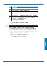
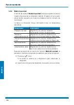
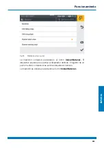
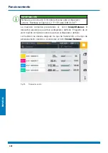
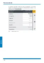
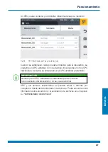
Страница 521: ...ESPA OL 521 Fig 55 Dispositivo Funcionamiento...

Страница 522: ...o de tel fono N mero de tel fono fijo N mero de tel fono m vil N mero de tel fono m vil El men contiene m s informaci n y opciones para editar la informaci n INFORMACI N La informaci n es voluntaria T...

Страница 523: ...formaci n Designaci n Descripci n Guardar y Reiniciar Backup de datos restaurar un backup de datos o restablecer el dispositivo a sus valores predeterminados Actualizaci n del software Leer y actualiz...

Страница 524: ...ESPA OL 524 6 12 4 Servicio El mosaico Servicio muestra los enlaces al sitio web del fabricante Fig 58 Sistema Funcionamiento...

Страница 525: ...n de hardware sistema operativo versi n del sistema operativo versi n del n cleo FCC CE Aprobaciones n mero de PTS M dulos de entrada Nombre n mero de serie c digo de pedido versi n de hardware versi...

Страница 526: ...so de un backup de datos se guardan todos los SPC incluso las mediciones plantillas y datos de medios y firmware actual en el dispositivo 1 Conecte un medio de almacenamiento por ejemplo una memoria U...

Страница 527: ...detiene El backup de datos podr a ser incompleto si el proceso se detiene Antes de iniciar el proceso aseg rese de que la bater a est cargada en al menos un 50 o el dispositivo est conectado al inter...

Страница 528: ...que cuando se restauran datos de un backup el firmware guardado en el backup tambi n se restaura 1 Conecte el medio de almacenamiento por ejemplo una memoria USB que contiene el backup de datos 2 Pres...

Страница 529: ...si el proceso se detiene Los datos restaurados podr an quedar incompletos si el proceso se detiene Antes de iniciar el proceso aseg rese de que la bater a est cargada en al menos un 50 o el dispositi...

Страница 530: ...ecto Verifique las conexiones por suciedad Siempre aseg rese que est instalada la ltima versi n de firmware en el dispositivo Podr encontrar m s informaci n sobre la actualizaci n del firmware en el C...

Страница 531: ...perderse si el dispositivo se reinicia Solo reinicie el dispositivo cuando sea absolutamente necesario 1 Presione el interruptor de encendido apagado y la tecla de funci n azul simult neamente durant...

Страница 532: ...el dispositivo haga un backup de los datos en el dispositivo Rem tase al Cap tulo Crear un Backup IMPORTANTE Todos los ajustes y par metros vuelven a sus valores predeterminados despu s de un reinicio...

Страница 533: ...r Antes de iniciar el proceso aseg rese de que la bater a est cargada en al menos un 50 o el dispositivo est conectado al interruptor principal mediante el adaptador de alimentaci n 4 Presione el bot...

Страница 534: ...incipal 1 Presione el bot n 2 Vaya a la opci n de men Ajustes Sistema Actualizaci n del software 3 Presione el bot n Verificar actualizaciones El dispositivo busca una actualizaci n de la versi n del...

Страница 535: ...o al interruptor principal mediante el adaptador de alimentaci n 5 Presione el bot n para iniciar la actualizaci n del firmware Se actualiza el firmware en el dispositivo Una barra de progreso indica...

Страница 536: ...Riesgo de da o a la propiedad Encaje todas las conexiones enroscadas en el dispositivo con sensores o tapas protectoras proporcionadas para garantizar el tipo de protecci n IP65 Nunca exponga el dispo...

Страница 537: ...a o material por sustancias agresivas o corrosivas Nunca use limpiadores abrasivos o vol tiles Nunca use agentes agresivos o corrosivos 9 2 Mantenimiento El dispositivo no requiere mantenimiento para...

Страница 538: ...Direcci n de correo electr nico N mero de art culo de la parte correspondiente del dispositivo versi n de firmware y n mero de serie de estar disponible Descripci n detallada de la falla IMPORTANTE R...

Страница 539: ...ue su dispositivo haya cumplido su vida til simplemente env elo dentro de su caja a trav s de un servicio de env o al punto de venta que le brinda soporte Tomamos las medidas de reciclaje y disposici...

Страница 540: ...529 2014 todas las conexiones enroscadas deben estar provistas de sensores o tapas protectoras Temperatura ambiente 10 50 C Temperatura de almacenamiento 20 60 C Humedad relativa 0 80 Carcasa ABS PC t...

Страница 541: ...Corriente de salida 3 75 A Potencia de salida 90 W 11 3 2 Fuente de alimentaci n interna Designaci n Propiedad Descripci n Tipo de bater a Bater a de i n litio Voltaje 14 4 VCC Capacidad 3350 mAh Dura...

Страница 542: ...10 20 50 125 250 500 800 1000 kBit s Solo en CAN Y Sensores CAN X M x 24 CAN de Webtec CANX1 CANX24 Sensores CAN Y M x 24 CAN de Webtec M x 5 CAN externo CANY1 CANY24 Velocidad de exploraci n canal P...

Страница 543: ...ransmisi n 12 MBit s Fuente de alimentaci n No Sin fuente de alimentaci n 11 5 2 Host USB Designaci n Propiedad Descripci n Enchufe 2 USB hembra Blindado tipo A Est ndar velocidad m xima de 2 0 Host 1...

Страница 544: ...res de Webtec Entradas INx 1 INx 2 INx 3 An logo Voltaje 12 VCC Fuente de alimentaci n M x 70 mA Fusible t rmico Fusible Protecci n contra sobretensiones protegido contra cortocircuitos Monitoreo acti...

Страница 545: ...cia de terminaci n de 120 entre TERMINAL 4 y TERMINAL 5 se puede desconectar a trav s del software Separaci n galv nica CAN alto CAN bajo y Tierra al dispositivo y CANx 1xx Interfaz Bus de medici n en...

Страница 546: ...eratura v ase el Bolet n T cnico de Accesorios del Registrador de datos hidr ulicos HPM 12 2 Est ndares t cnicos Est ndar EMC EN61326 1 2013 EN 55011 2009 EN 61000 3 2 2014 3 2013 EN 61000 4 2 2009 3...

Страница 547: ...ESPA OL 547 12 3 Plano de dimensiones Ap ndice...

Страница 548: ...ESPA OL 548 Ap ndice...

Страница 549: ...ESPA OL 549 Ap ndice...

Страница 550: ...FORMACI N Se necesita la informaci n en la placa de caracter sticas en caso de consultas dirigidas a su punto de venta 12 5 Certificados Se brindan certificados b sicos y la Declaraci n de Conformidad...

Страница 551: ...7000 IM CAN 445 Fig 12 Conexi n de los sensores 448 Fig 13 Uso del soporte plegable 449 Fig 14 Ensamblaje del soporte 450 Fig 15 Formato de la pantalla 456 Fig 16 Men de Inicio r pido 458 Fig 17 Tecla...

Страница 552: ...cto de Servicio 2 499 Fig 41 Crear un SPC Contenedor de Proyecto de Servicio 3 500 Fig 42 Men 501 Fig 43 Administrador de Archivos 502 Fig 44 Administraci n de archivos 503 Fig 45 Sensores 504 Fig 46...

Страница 553: ...ESPA OL 553 Ap ndice...

Страница 554: ......

Страница 555: ...1 4 563 2 564 2 1 564 2 1 1 564 2 1 2 565 2 2 566 2 3 568 2 4 569 3 570 3 1 571 3 2 572 3 3 573 3 3 1 CAN CAN 574 3 3 2 D IN D OUT F1 F2 576 3 4 577 4 578 4 4 1 579 4 4 2 HPM7000 IM ANO HPM7000 IM AN...

Страница 556: ...1 584 5 2 585 5 3 586 5 4 587 5 5 588 6 590 6 1 590 6 1 1 591 6 2 594 6 2 1 595 6 2 2 596 6 2 3 598 6 2 4 600 6 2 5 602 6 2 6 603 6 3 604 6 3 1 6 605 6 3 2 12 606 6 3 3 607 6 3 4 608 6 3 5 611 6 3 6...

Страница 557: ...5 3 622 6 5 4 624 6 5 5 627 6 5 6 630 6 6 633 6 7 634 6 7 1 SPC 634 6 7 2 SPC 636 6 8 639 6 9 640 6 9 1 641 6 10 642 6 10 1 CAN X 644 6 10 2 CAN Y 644 6 10 3 D IN D OUT F1 F2 646 6 10 4 A B 650 6 10 5...

Страница 558: ...6 12 1 658 6 12 2 660 6 12 3 661 6 12 4 662 6 12 5 663 6 13 664 6 14 666 7 668 7 1 669 7 2 670 7 3 672 8 674 9 675 9 1 675 9 2 675 9 3 676 10 677 11 678 11 1 678 11 2 678 11 3 678 11 3 1 679 11 3 2 6...

Страница 559: ...IN D OUT F1 F2 680 11 4 3 680 11 5 681 11 5 1 USB 681 11 5 2 USB 681 11 5 3 LAN 681 11 6 HPM7000 IM ANO HPM7000 IM ANI 682 11 6 1 SR 682 11 6 2 682 11 7 CAN HPM7000 IM CAN 683 12 684 12 1 684 12 2 68...

Страница 560: ...560 HPM7000 Safety Information 1...

Страница 561: ...561 1 HPM7000 CAN HPM7000 HPM7000 USB LAN HPM7000 1 HPM7000...

Страница 562: ...562 1 1 HPM7000 CAN 1 2 94 9 EC...

Страница 563: ...563 1 3 CE 1 4 HPM7000 HPM7000 AC PSU 110 240VAC 24VDC 3 750mA EN USB 2 0...

Страница 564: ...564 2 2 1 2 1 1...

Страница 565: ...565 2 1 2...

Страница 566: ...566 2 2...

Страница 567: ...567...

Страница 568: ...568 2 3...

Страница 569: ...569 2 4...

Страница 570: ...570 3 Input Modules...

Страница 571: ...571 3 1 1 2 3 4 6 7 8 5 2 1 CAN X CAN Y D IN D OUT F1 F2 2 A 3 B 4 2 USB 1 USB LAN 5 6 7 8...

Страница 572: ...572 3 2 LAN VESA...

Страница 573: ...573 3 3 8 7 6 5 4 3 2 1 3 1 24VDC 2 CAN CAN X CAN 3 CAN CAN Y CAN 4 D IN D OUT F1 F2 5 USB 6 USB 1 7 USB 2 8 LAN HPMComm LAN USB...

Страница 574: ...574 3 3 1 CAN CAN CAN X CAN Y CAN Y 24 CAN 24 4 3 5 2 1 4 CAN X CAN Y 1 2 Ub 24 VDC 3 4 CAN 5 CAN CAN X CAN Y CAN...

Страница 575: ...575 CAN Y 5 CAN CAN CAN CAN CANopen CAN Generic CAN Sensors CAN CAN CAN CAN Y Sensors...

Страница 576: ...576 3 3 2 D IN D OUT F1 F2 D IN D OUT F1 F2 2 Sensors 1 2 5 3 4 5 D IN D OUT F1 F2 D IN D OUT F1 F2 1 1 2 1 3 2 4 2 5 Ub 24 VDC Ub 24 VDC...

Страница 577: ...577 3 4 2 1 6 1 A 2 B Input Modules...

Страница 578: ...578 4...

Страница 579: ...579 4 4 1 1 A 1 2 3 2 4 1 1 2 7...

Страница 580: ...580 4 4 2 HPM7000 IM ANO HPM7000 IM ANI HPM7000 IM ANO HPM7000 IM ANI IN1 3 SR IN4 5 IN4 5 HPM7000 IM ANI 1 2 3 4 8 HPM7000 IM ANO HPM7000 IM ANI 1 IN1 2 IN2 3 IN3 4 IN4 5...

Страница 581: ...581 IN4 5 1 2 5 3 4 9 HPM7000 IM ANO HPM7000 IM ANI 1 Ub 24 VDC 2 1 IN4 3 4 2 IN5 5 IN1 IN3 Input Modules A and B...

Страница 582: ...582 4 4 3 CAN HPM7000 IM CAN CAN HPM7000 IM CAN CAN CAN CAN CAN SAE J1939 CAN CAN CAN 1 2 10 CAN HPM7000 IM CAN 1 CAN CAN1xx 2 CAN CAN2xx...

Страница 583: ...583 1 2 5 3 4 11 CAN HPM7000 IM CAN 1 2 3 4 CAN 5 CAN Input Modules A and B...

Страница 584: ...584 5 5 1 HPM7000 AC PSU 10 90 Mechanical Data...

Страница 585: ...585 5 2 1 1 5 1 2...

Страница 586: ...586 5 3 12 1 2 Y 3...

Страница 587: ...587 5 4 40 13 1 2...

Страница 588: ...588 5 5 VESA 100 mm 100 mm 14...

Страница 589: ...589 1 VESA VESA 2 VESA 3 6 mm VESA M4...

Страница 590: ...590 6 6 1...

Страница 591: ...591 6 1 1...

Страница 592: ...592...

Страница 593: ...593 Screen Design...

Страница 594: ...594 6 2 1 2 3 7 5 6 8 4 15 1 2 3 4 5 6 7 8...

Страница 595: ...595 6 2 1 USB1 USB2 HPMComm...

Страница 596: ...596 6 2 2 16 USB 1 USB 2...

Страница 597: ...597 1 2...

Страница 598: ...598 6 2 3 17 QWERTZ QWERTY AZERTY Device...

Страница 599: ...599 18 19...

Страница 600: ...600 6 2 4...

Страница 601: ...601...

Страница 602: ...602 6 2 5 20 21...

Страница 603: ...603 6 2 6 1 2 2 D IN D IN D OUT D OUT 3...

Страница 604: ...604 6 3 Edit Channels 1...

Страница 605: ...605 6 3 1 6 6 6 1 2 3 4 5 6 22 6 1 CANY 1 24 CANX 1 24 2 3 4 5 6...

Страница 606: ...606 6 3 2 12 12 12 12 1 2 23 12 1 2...

Страница 607: ...607 6 3 3 4 1 2 4 6 3 5 7 8 8 24 1 2 3 4 5 6 7 FS 8...

Страница 608: ...608 6 3 4 8 1 2 3 4 25 1 2 3 4...

Страница 609: ...609 8 1 2 X Y 26 1 2 3 X Y...

Страница 610: ...610 1 2 3 100...

Страница 611: ...611 6 3 5 1 2 6 3 5 4 27 1 2 3 4 B 5 6 A...

Страница 612: ...612 1 File Manager 28 2 3 X Y 4...

Страница 613: ...613 1 2 3 4 5 6 1 X 2 X 3 A 4 B 5 X 6 Y A B...

Страница 614: ...614 6 3 6 1 2 1 2 3 4 5 6 7 29...

Страница 615: ...615 1 2 3 4 5 6 7 3 4 5...

Страница 616: ...616 30...

Страница 617: ...617 6 4 1 2...

Страница 618: ...618 6 5 IN4 IN5 1 2 31...

Страница 619: ...619 6 5 1 1...

Страница 620: ...620 6 5 2 1 2...

Страница 621: ...621 32...

Страница 622: ...622 6 5 3 D IN D IN 1 2...

Страница 623: ...623 33...

Страница 624: ...624 6 5 4 1 2...

Страница 625: ...625 34...

Страница 626: ...626 D IN D IN D OUT F1 F2 35...

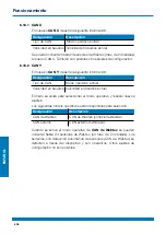
Страница 627: ...627 6 5 5 A A B A B C C D C D A B C D...

Страница 628: ...628 1 2 D IN D IN D OUT F1 F2...

Страница 629: ...629 36...

Страница 630: ...630 6 5 6 100 16 1ms Input Modules A and B 1 2...

Страница 631: ...631 D IN D IN D OUT F1 F2...

Страница 632: ...632 37...

Страница 633: ...633 6 6 1 Switching the Device On and Off 2 Connecting the Sensors 3 Edit Channels 4 Measuring Methods 5 6 SPC Project Management File Manager...

Страница 634: ...634 6 7 SPC SPC U 6 7 1 SPC SPC SPC PDF videos MPEG 4 etc SPC...

Страница 635: ...635 38 SPC SPC SPC SPC SPC SPC File Manager...

Страница 636: ...636 6 7 2 SPC SPC 1 Connecting the Sensors 2 Edit Channels 3 39 SPC 1...

Страница 637: ...637 4 5 6 7 SPC 40 SPC 2 SPC SPC SPC SPC...

Страница 638: ...638 8 SPC 9 SPC 41 SPC 3 10 SPC 11 SPC...

Страница 639: ...639 6 8 42 PDF File Manager Sensors Connections Settings...

Страница 640: ...640 6 9 SPC 1 2 3 43 1 2 USB1 USB1 3 USB2 USB2 SPC...

Страница 641: ...641 6 9 1 SPC 44 SPC...

Страница 642: ...642 6 10 A B 1 2 3 6 5 4 45...

Страница 643: ...643 1 CAN X CAN X 2 CAN Y CAN Y 3 D IN D OUT F1 F2 4 5 IM CAN SAEJ B 6 IM A...

Страница 644: ...644 6 10 1 CAN X CAN X CAN 24 24 CAN X 6 10 2 CAN Y CAN Y CAN CAN CAN CAN CAN CANopen CAN 24 24 CAN...

Страница 645: ...645 CAN CAN 5 5 CANopen PDO CAN Generic 46 CAN Y CAN...

Страница 646: ...646 6 10 3 D IN D OUT F1 F2 D IN D OUT F1 F2 D IN D IN D OUT D OUT D IN D OUT 1 2 D IN 0 1 D IN D OUT 0 1 D OUT 47 D IN D OUT F1 F2...

Страница 647: ...647 D IN 0 1 D OUT 0 1 A A B A B A B...

Страница 648: ...648 NCLS 0 0 2 V 1 NOPN 1 0 0 2 V...

Страница 649: ...649 1 1 2 2...

Страница 650: ...650 6 10 4 A B The A B 48...

Страница 651: ...651 1 HPM7000 IM ANO HPM7000 IM ANI IN4 5 1 2 5 3 4 Fig 49 1 Ub 24 VDC 2 1 IN4 3 4 2 IN5 5 2 IN1 IN3...

Страница 652: ...652 6 10 5 1 1 2 2 3 3 4 4 1 2...

Страница 653: ...653 50...

Страница 654: ...654 6 11 1 2 51 1 LAN 2...

Страница 655: ...655 6 11 1 LAN LAN LAN 52...

Страница 656: ...656 6 11 2 IP IP 8 VNC 53 LAN IP...

Страница 657: ...657 6 12 1 2 3 5 4 54 1 2 3 4 5...

Страница 658: ...658 6 12 1 QWERTZ QWERTY AZERTY...

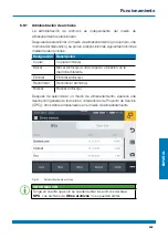
Страница 659: ...659 55...

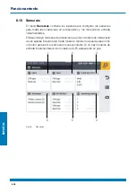
Страница 660: ...660 6 12 2 56...

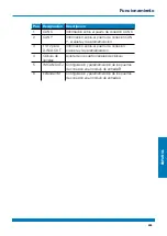
Страница 661: ...661 6 12 3 Creating a Backup Resetting the Device to its Default Settings 57...

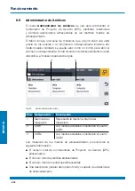
Страница 662: ...662 6 12 4 58...

Страница 663: ...663 6 12 5 FCC CE PTS USB1 USB2 59...

Страница 664: ...664 6 13 SPC 1 U 2 3 4...

Страница 665: ...665 5 USB1 50 6...

Страница 666: ...666 6 14 1 U 2 3 4...

Страница 667: ...667 5 USB1 6 50 7...

Страница 668: ...668 7 Updating the Firmware...

Страница 669: ...669 7 1 1 3 2 60 61...

Страница 670: ...670 7 2 Creating a Backup 1 2 3...

Страница 671: ...671 50 4...

Страница 672: ...672 7 3 U U 1 2 3 4...

Страница 673: ...673 50 5 6...

Страница 674: ...674 8 10 90 Mechanical Data IP65...

Страница 675: ...675 9 9 1 9 2...

Страница 676: ...676 9 3...

Страница 677: ...677 10...

Страница 678: ...CAN 24 CAN X 24 1 24 CAN Y 24 1 1 D IN 1 D IN 1 1 1 D OUT 1 D OUT 1 1 2 2 1 11 2 282 195 85 mm 1 880 g IP65 EN IEC 60529 2014 10 50 C 20 60 C 0 80 ABS PC TPE VESA 100 mm 100 mm M4 40 2 11 3 P Cap 800...

Страница 679: ...679 11 3 1 3 Binder 719 GT 41133 9028 4 0 T2 100 240 V 50 60 Hz 24 V 3 75 A 90 W 11 3 2 14 4 VDC 3350 mAh 6 24 20 mA 11 3 3 I MX6 12 GB SD 250 16 000 000...

Страница 680: ...20 50 125 250 500 800 1000 kBit s CAN Y CAN X 24 CAN CANX1 CANX24 CAN Y 24 CAN 5 CAN CANY1 CANY24 P 1 1 1 000 4 P 2 2 5 11 4 2 D IN D OUT F1 F2 2 1 D IN 1 D OUT 1 F1 1 F2 5 M12 1 SPEEDCON 24 VDC 80 mA...

Страница 681: ...681 11 5 11 5 1 USB USB B 2 0 12 MBit s 11 5 2 USB 2 USB A 2 0 1 2 12 MBit s 64 GB 5 VDC 450 mA VCC 11 5 3 LAN RJ45 10 100 MBit s IEEE 802 3 10 100BaseT...

Страница 682: ...M12 1 INx 1 INx 2 INx 3 INx 4 INx 5 24 VDC HPM7000 IM ANI 250 mA RS 422 ABS PC TPE IP65 10 50 C 20 60 C 11 6 1 SR 3 5 ODU INx 1 INx 2 INx 3 12 VDC 70 mA 0 1 3 4 V 3 4 V 1 1 000 11 6 2 1 5 M12 1 INx 4...

Страница 683: ...x 1xx CANx 2xx 5 M12 1 SPEEDCON CANx 1xx PIN 4 PIN 5 120 CANx 2xx CAN CAN CANx 2xx PIN 4 PIN 5 120 CANx 1xx CAN CAN RS 422 CANopen PDO SAE J1939 CAN Generic CAN 1000 kBit CAN1xx 24 CAN2xx 24 P 1 1 1 0...

Страница 684: ...06 4 2012 5 2014 6 2014 11 2004 ETSI EN 301 489 1 V2 1 1 ETSI EN 301 489 19 V2 1 0 ETSI EN 300 328 V2 1 1 ETSI EN 301 511 V9 0 2 ETSI EN 301 908 1 V11 1 1 ETSI EN 300 440 V2 1 1 ETSI EN 303 413 V1 1 1...

Страница 685: ...685 12 3...

Страница 686: ...686...

Страница 687: ...687...

Страница 688: ...688 12 4 12 5...

Страница 689: ...6 6 577 7 579 8 HPM7000 IM ANO HPM7000 IM ANI 580 9 HPM7000 IM ANO HPM7000 IM ANI 581 10 CAN HPM7000 IM CAN 582 11 CAN HPM7000 IM CAN 583 12 586 13 587 14 588 15 594 16 596 17 598 18 599 19 599 20 602...

Страница 690: ...25 35 626 36 629 37 632 38 SPC 635 39 SPC 1 636 40 SPC 2 637 41 SPC 3 638 42 639 43 640 44 641 45 642 46 CAN Y 645 47 D IN D OUT F1 F2 646 48 650 49 651 50 653 51 654 52 655 53 656 54 657 55 659 56 66...

Страница 691: ......

Страница 692: ...btec beh lt sich das Recht vor Verbesserungen oder nderungen der Spezifikationen ohne Ank ndigung vorzunehmen Webtec se r serve le droit d am liorer et de changer ses sp cifications sans pr avis Webte...

Отзывы: