background image

21

Please Do Not Return This Product To The Store. 

Contact your local Wayne-Dalton dealer. To find your local Wayne-Dalton dealer, refer to your 

local yellow pages/business listings or go to the 

Find a Dealer

 section online at 

www.wayne-dalton.com

Tools Needed:

iNST

alla

Tio

N

22

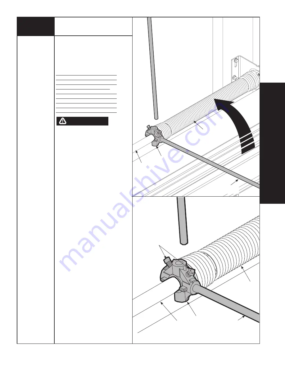
Position a ladder slightly to the side of spring 

so that the winding cone is easily accessible, 

yet your body is not in direct line with the 

winding bars. Check the label attached to the 

spring warning tag for the required number 

of complete turns to balance your door. 

6’0” Door height = Approx 7-1/8 Turns

6’3” Door height = Approx 7-1/2 Turns

6’6” Door height = Approx 7-3/4 Turns

6’9” Door height = Approx 8 Turns

7’0” Door height = Approx 8-1/4 Turns

7’3” Door height = Approx 8-5/8 Turns

7’6” Door height = Approx 8-7/8 Turns

7’9” Door height = Approx 9-1/4 Turns

8’0” Door height = Approx 9-1/2 Turns

PRIOR TO WINDING OR MAKING 

ADjUSTMENTS TO ThE SPRINGS, ENSURE 

YOU’RE WINDING IN ThE PROPER DIRECTION 

AS STATED IN ThE INSTALLATION 

INSTRUCTIONS. OThERWISE, ThE SPRING 

FITTINGS MAY RELEASE FROM SPRING IF 

NOT WOUND IN ThE PROPER DIRECTION AND 

COULD RESULT IN SEVERE OR FATAL INjURY. 

Alternately inserting the winding bars into the 

holes of the spring’s winding cone, rotate the 

winding cone upward toward ceiling, 1/4 turn 

at a time, until the required number of 

complete turns for your door height is 

achieved. As the last 1/4 turn is achieved, 

securely hold winding bar while tightening 

both set screws in winding cone to 14-15 ft. 

lbs. of torque (Once set screws contact the 

tube, tighten screws one full turn). 

Carefully remove winding bar from winding 

cone. Proceed to wind the second spring in 

the same manner. While holding the door 

down, to prevent it from rising unexpectedly, 

in the event the spring(s) were overwound, 

carefully remove the locking clamps from the 
torsion tube and the vertical tracks. 

imPoRTaNT:

 CAUTIOUSLY REMOVE 

LOCKING PLIERS FROM ThE TORSION 

TUBE AND LOCKING CLAMPS FROM ThE 
VERTICAL TRACKS. 

Adjustments to the required from the number 

of turns stated may be necessary. If door 

raises off floor under spring tension alone, 

Reduce spring tension until door rests on the 

floor. If the door is hard to raise or drifts 

down on its own, add spring tension. An 

unbalanced door such as this can cause 

garage door opener operation problems. 

winding Torsion Spring(s)

Power Drill

3/16” Drill Bit

7/16” Socket 

Driver

Phillips head 

Screwdriver

Step Ladder

APPROVED 

WINDING BARS

WINDING 

CONE

SPRING

TORSION 

TUBE

APPROVED 

WINDING BARS

SET 

SCREWS

WINDING 

CONE

SPRING

TORSION 

TUBE

waRNiNg

Содержание 8800 Aluminum Full View

Страница 1: ...about any of the procedures do not perform the work Instead have a qualified door agency do the installation or repairs 2009 Wayne Dalton Corp Part No 338303 REV1 08 03 2009 Torsion Spring Installation Instructions and Owner s Manual Portland Source Plant Wayne Dalton Corp P O Box 67 Mt Hope OH 44660 www wayne dalton com ...

Страница 2: ...tion to any part of the door especially to springs spring brackets bottom corner brackets red colored fasteners cables or supports To avoid possible severe or fatal injury have any such work performed by a trained door systems technician using proper tools and instructions 12 On electrically operated doors pull down ropes must be removed and locks must be removed or made inoperative in the open un...

Страница 3: ...t bottom brackets As required 6 screw eye and pull rope as required LIFT HANDLEs as required jamb brackets as required mANUAL 8800 8850 Aluminum Full View IMPORTANT NOTICE Read these instructions carefully before attempting installation If in question about any of the procedures do not perform the work Instead have a qualified door agency do the installation or repairs Copyright 2008 Wayne Dalton ...

Страница 4: ...ad bolts 5 16 X 2 HEX head LAG screws as required The bottom section can be identified by the factory attached bottom astragal or by the bottom bracket warning labels on each end stile This section is always the 1st section on four and five section doors The lock section may have a yellow and black warning label on the right side of the section This section is always the 2nd section on four and fi...

Страница 5: ...grips Step Ladder Tape Measure level vice clamps pencil 9 32 1 2 3 16 1 8 drill bits Counterbalance spring tension must always be released before any attempt is made to start removing an existing door A POWERFUL SPRING RELEASING ITS ENERGY SUDDENLY CAN CAUSE SEVERE OR FATAL INJURY TO AVOID INJURY HAVE A TRAINED DOOR SYSTEMS TECHNICIAN USING PROPER TOOLS AND INSTRUCTIONS RELEASE THE SPRING TENSION ...

Страница 6: ...ng surface Any wood found not to be sound must be replaced For Torsion spring applications a suitable mounting surface must be firmly attached to the wall above the header at the center of the opening The mounting surface must be 2 x 6 lumber minimum Select southern yellow pine lumber Do not use lumber marked as spruce pine fur or SPF The mounting surface must be securely attached to the wall with...

Страница 7: ...checking the opening It must be the same size as the door Vertical jambs must be plumb and level with header Important STAINLESS STEEL OR PT 2000 COATED LAG SCREWS NOT SUPPLIED MUST be USED When INSTALLING CENTER bearing brackets END brackets jamb brackets OPERATOR MOUNTING SUPPORT brackets AND DISCONNECT brackets ON TREATED Lumber PRESERVATIVE TREATED STAINLESS STEEL OR PT 2000 COATED LAG SCREWS ...

Страница 8: ...ep Vertical track must be cut to the proper length prior to installation IMPORTANT Doors that are 7 0 or 8 0 in height do not require cutting the vertical track Determine the radius of your horizontal track NOTE All Portland tracks have the radius stamped on the side of the track Using this measurement refer to the vertical track cutting chart to determine the length of the vertical track Cut the ...

Страница 9: ...jamb bracket with the slot above the quick install features in the vertical track The long side of the bracket is placed against the track Fasten the jamb bracket finger tight using 1 1 4 20 x 5 8 carriage bolt and 1 1 4 20 flange hex nut To attach the top jamb bracket JB 3 locate the third set of quick install features of the vertical track Align the slot in the jamb bracket with the slot above t...

Страница 10: ...tom Bracket 5 IMPORTANT RIGHT AND LEFT HAND IS ALWAYS DETERMINED FROM INSIDE THE GARAGE LOOKING OUT NOTE for door section identification see page 4 Bottom brackets are right and left hand Locate the bottom section place the left hand bottom bracket flush against the bottom left hand corner Secure the bottom bracket to the sec tion using 1 1 4 x 5 8 tamper resistant self drilling screw and 2 1 4 x ...

Страница 11: ...1 4 x 5 8 Carriage Bolts and 2 1 4 Flanged Hex Nuts Repeat for each of the pre drilled locations along the reinforcing fin Center Hinges Place 1 1 end hinge at each of the center stiles Vertically align the slot hole of the lower numbered leaf with the small groove in the center stiles and the center of the hinge with the top edge of the section Secure the center hinges to the section using 2 1 4 ...

Страница 12: ...cket base top section top bracket assembly 1 3 8 16 hex nut 1 3 8 16 x 3 4 Hex head bolt top bracket slide 9 Lift Handle Bottom section Locate the center most stile of the bottom section of the door On the inside of the door center the lift handle vertically with the center stile horizontally on the bottom section rail and within 8 of the bottom of the section Using the lift handle as a template p...

Страница 13: ...ill 7 16 Socket Driver Tape Measure Level Step Ladder BOTTOM SECTION 5 16 x 2 LAG SCREWS fLAGANGLE VERTICAL TRACK ASSEMBLY JAMB BRACKET vertical track roller jamb bracket 5 16 x 2 lag bolt IMPORTANT The tops of the vertical tracks must be level from side to side If the bottom section was shimmed to level it The vertical track on the shimmed side must be raised the height of the shim Position the l...

Страница 14: ... remaining section s except top section in same manner Now flip up hinge leaf hold tight against section and fasten center hinges first and end hinges last using 2 1 4 x 7 8 self drilling screws Repeat for other section s except top section IMPORTANT Push hold the hinge leaf against section while securing with 1 4 x 5 8 self tapping screws NOTE Install lock at this time sold separately see instruc...

Страница 15: ... 7 When installing a door with a torsion counterbalance system vertical track alignment is critical Position flagangle between 1 11 16 43 mm to 1 3 4 44 mm from the edge of the door Tighten the bottom lag screw Flagangles must be parallel to the door sections Repeat for opposite side IMPORTANT THE DIMENSION BETWEEN THE FLAGANGLES MUST BE DOOR WIDTH PLUS 3 3 8 86MM TO 3 1 2 89 MM FOR SMOOTH SAFE DO...

Страница 16: ...NOT RAISE DOOR UNTIL HORIZONTAL TRACKS ARE SE CURED AT REAR AS OUTLINED IN STEP 23 OR DOOR COULD FALL FROM OVERHEAD POSI TION CAUSING SEVERE OR FATAL INJURY Tools Needed 15 14 With tracks installed you can adjust the top brackets Vertically align the top section of the door with the lower sections Once aligned position the roller in the top bracket slide out against the horizontal track Maintainin...

Страница 17: ...Bit Step Ladder Measure to locate the center of the door and mark a vertical pencil line on the mounting surface above the door to indicate the center line of the door Then measure from the center of the bearing in one of the end bearing brackets DOWN to the top of the door Using that dimension measure UP from the top of the door and mark a horizontal pencil line on the mounting surface intersecti...

Страница 18: ...orsion counterbalance winding cones and cable drums are now colored red DO NOT identify right and left hand by the set screw color Slide the nylon center bushing onto the torsion tube followed by the springs and cable drums The nylon center bushing springs and cable drums must be positioned as shown With assistance pick up the torsion assembly and slide one end of the tube through one end bearing ...

Страница 19: ...cure the spring s to the center bearing bracket with 2 3 8 16 x 1 1 2 hex head bolts and 2 3 8 16 hex nuts IMPORTANT Springs under tension can be dangerous IMPORTANT The spring warning tag s supplied must be securely attached to the stationary spring cone in plain view Should a replacement spring warning tag be required contact Wayne Dalton Corp for free replacements Nylon Center Bushing Torsion S...

Страница 20: ...ube and brace vice grips against jamb to keep cable taut Slide the right hand cable drum against the right hand end bearing bracket and rotate drum until cable is taunt Tighten set screws in right hand cable drum to 14 15 ft lbs of torque Once set screws contact the tube tighten screws one full turn IMPORTANT Check each cable making sure both are seated properly on the cable drums and have equal c...

Страница 21: ...ng bars into the holes of the spring s winding cone rotate the winding cone upward toward ceiling 1 4 turn at a time until the required number of complete turns for your door height is achieved As the last 1 4 turn is achieved securely hold winding bar while tightening both set screws in winding cone to 14 15 ft lbs of torque Once set screws contact the tube tighten screws one full turn Carefully ...

Страница 22: ... may not be supplied fabricate rear support for horizontal tracks Attach horizontal tracks to the rear supports with 5 16 18 x 1 1 4 hex bolts and nuts may not be supplied Horizontal tracks must be level and parallel with door NOTE If rear supports are to be installed over drywall use 5 16 x 2 hex head lag screws and make sure lag screws engaged solid structural lumber NOTE If an idrive opener wil...

Страница 23: ...still does not operate easily lower the door into the closed position UNWIND THE SPRING S FULLY Refer to P1 on page 5 Removing an old door and recheck the following items 1 Check the door for level 2 Check the torsion tube for level 3 Check the track spacing 4 Check the counterbalance cables for equal tension 5 Check the track for potential obstruction of the rollers 6 Clamp locking pliers onto tr...

Страница 24: ...ock assembly with the door section and align with the square hole in the vertical track The side lock should be spaced in approximately 1 8 from the section edge IMPORTANT side locks must be removed or made inoperative in the unlocked position if an operator is installed on the door NOTE After completing this step continue with step 12 on page 14 1 8 DO NOT INSTALL PULL ROPES ON DOORS WITH ELECTRI...

Страница 25: ...RIC EYE SYSTEM THEN THIS MUST BE TESTED AT THE SAME TIME TO ENSURE THAT DOOR DOES NOT CLOSE AND A CLOSING DOOR OPENS IF PHOTOELECTRIC EYE SYSTEM IS OBSTRUCTED FAILURE TO MAKE ADJUSTMENTS IF NECESSARY CAN RESULT IN SEVERE OR FATAL INJURY 1 Install operator rail 1 2 to 1 1 2 13 38 mm above high arc of top section of the door 2 Mount operator to ceiling so that 1 to 1 1 2 25 38 mm clearance is mainta...

Страница 26: ...ing solution is recommended A mild detergent solution consisting of one cup detergent with less than 0 5 phosphate dissolved into five gallons of warm water will aid in the removal of most dirt NOTE The use of detergents containing greater than 0 5 phosphate is not recommended for use in general cleaning of garage doors NOTE Be sure to clean behind weather stripping on both sides and top of door C...

Страница 27: ...limitations may not apply to you Any claim under this Limited Warranty must be made in writing within the applicable warranty period to the dealer from which the product was purchased Unless the dealer is no longer in business a written claim to the Manufacturer will be the same as if no claim had been made at all At the Manufacturer s option pursuant to the dealer having notified the Manufacturer...

Страница 28: ...86 7 036 548 7 059 380 7 121 317 7 128 123 7 134 471 7 134 472 7 219 392 7 254 868 Canadian 2 384 936 2 477 445 2 495 175 2 507 590 2 530 701 2 530 74 2 2 532 824 Other US and Foreign Patents pending Contact your local Wayne Dalton dealer To find your local Wayne Dalton dealer refer to your local yellow pages business listings or go to the Find a Dealer section online at www wayne dalton com Thank...

Отзывы: