6
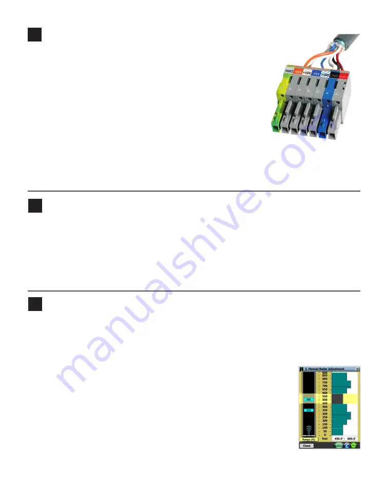
Terminate the 6-conductor cable into the terminal block section
Terminate the sensor cable into one of the four ports on the back of the Click 650. For
each sensor you want to connect to the Click 650, do the following:
1
Remove one of the plugs from the back (they are numbered 1–4; you’ll
need to keep track of which sensor is plugged into which port).
2
Terminate the conductors from the cable into that plug, following the labels
on the plug (as shown at right), then reconnect the plug to the Click 650.
3
Each sensor port has a corresponding RJ-11 jack, LED, and switch on
the faceplate of the Click 650. Make sure the switch is turned on.
4
On the faceplate of the device is an SDLC port; connect a cable there to
connect the Click 650, and its attached sensors, to the SDLC bus and, via
that bus, to the controller.
NOTE.
If your cabinet doesn’t support SDLC, you can connect from the sensor port RJ-11 jacks to contact
closure cards and communicate with the controller that way.
7
Connect SmartSensor Manager Advance to the sensor
1
Make a physical or wireless connection to the sensor; generally you do this via a Click 650 or other
Click device that has a communication connection with the sensor—for instance, you could connect to
an Ethernet device on the same T-bus as the Click 222 surge protector the sensor is connected to.
2
Download SmartSensor Manager Advance from www.wavetronix.com/support.
3
Launch SSMA and click
Communication
on the main menu. Based on the kind of connection you’re
making, go to the
Serial
or
Internet
tab.
4
Change any necessary settings, such as port, speed or address, and click
Connect
.
8
Enter installation details and configure sensor
1
Select
Sensor Configuration
from the main menu, then
1. Installation Details
.
2
Make sure your alignment is accurate enough to detect vehicles for dilemma zone protection. Use the
controls on the right to record where the sensor is in relation to the stop bar and lanes of interest. Use
the
Traffic
button to change the direction of traffic.
3
Click
OK
to save your changes.
Follow the steps below to automatically configure the SmartSensor Advance:
1
Select
2. Automatic Radar Configuration
from the main menu.
2
Click the
Play
button. The sensor will need to detect free flowing traffic in order to
finish the configuration.
3
Click the
Close
button once the sensor is configured.
4
Click on the
3. Manual Radar Adjustment
link to adjust the sensor thresholds, if
necessary. When the sensor has detected enough vehicles, there should be some
variation to the thresholds. If the thresholds are all the same, go back to step 2 and
click
Play
while more vehicles are traveling down the approach.
5
Make the sensitivity level adjustments and click
Enter
.
6
Click the
OK
button to accept the modifications and close the Edit Sensitivity Thresholds window.


