


6 of 23
WX-501-0552 • 01.22
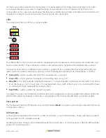
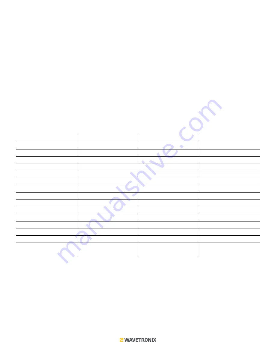
Fault State
The Click 111 receives datagrams from the connected SmartSensor, and it’s looking for datagrams containing
detection data that’s intended for one of its output channels. If a bus does not receive such a datagram for ten
seconds, it will go into a fault state. (The fault timeout can be changed using Click Supervisor software, as will be
discussed later.) Each data bus can go into a fault state independently. The state of the output channels, when
they are in fault, can be configured as either a call or a no call.
If either of the buses go into a fault state then the master fault will be asserted. The card has one master fault
indicator (the blue LED on the faceplate of the device) and an associated output on the back connector. You can
disable failsafe for the whole card if you desire.
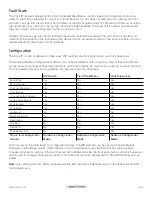
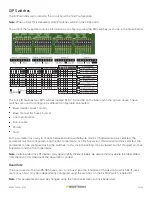
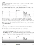
Configuration
The Click 111 can be configured in three ways: DIP switches, the front panel menu, and Click Supervisor.
These three different configuration methods can configure different sets of options; some of these parameters
can be set using multiple configuration methods, and some of them can only be set using one particular method.
The table below lists how each parameter may be accessed and configured.
DIP Switch
Front Panel Menu
Click Supervisor
Baud Rate
Yes
Yes
Yes
Base Channel
Yes
Yes
Yes
Channel Allocation
Yes
Yes
Yes
Data Enable
Yes
Yes
Yes
Channel Output Polarity
Yes
Yes
Yes
Fault Output Polarity
Yes
Yes
Yes
Fault Enable
Yes
Yes
Yes
Fault State
Yes
Yes
Yes
Autobaud
No
Yes
No
Reset to Defaults
No
Yes
Yes
Description
No
No
Yes
Location
No
No
Yes
Device ID
No
No
Yes
Fault Detect Time
No
No
Yes
To use this configuration
feature:
Hardware Configuration
Mode
Software Configuration
Mode
Software Configuration
Mode
The final row on the table refers to configuration modes. The DIP switches can be used to choose between
Hardware and Software modes. If the switches are set to Hardware mode, the DIP switches will be used to
change configuration options. If the switches are set to Software mode, the front panel menu and Click Supervisor
will be used to change configuration options. This will be discussed in greater detail in the DIP Switches section
below.
Note.
Any setting which has been configured via the DIP switches will be read-only in Click Supervisor and the
front panel menu.


