background image

CARDIO WAVE EXCITE Class & Trend: Service & maintenance manual- rev.2.0 


Pagina 5.1 

5. 


INSTALLATION INSTRUCTIONS 

5.1. 


SPECIFICATIONS AND REQUIREMENTS 

For correct machine installation, make sure that: 

 
1.


The machine is installed on a level surface that is free of vibrations and has sufficient carrying 
capacity for the combined weight of the machine and user. 

 
2.


The place of installation is free of dust and sand. 

 
3.


The place of installation meets the operating temperature and humidity conditions specified in 
paragraph: 2.5. “Ambient specifications”. 

 
4.


The machine is not positioned close to sources of heat, sources of electromagnetic noise 
(television sets, electrical motors, antennas, high voltage lines, household appliances, etc...) or 
medical equipment. 

 
5.


To eliminate any interference with the cardio receiver, no transmitters should be placed less 
than 90cm from the display. 


Only for the 500, 700 and 700WTV models: 

 
6.


The mains voltage must match the value specified on the machine rating plate. 

 
7.


The electrical system must be correctly earthed. 

 
8.


The wall outlet used should be reserved for the machine and have a rating of at least 100VA. 

 
9.


The maximum number of machines connected in cascade should be that indicated in paragraph 
3.1.11. “Power entry module”. 

 
10.


Position the mains lead of the machine where it will not be underfoot. 

Содержание CLASS & TREND

Страница 1: ...SERVICE MAINTENANCE MANUAL REV 2 0 ...

Страница 2: ......

Страница 3: ...S PRESENT NOTE The information contained in this document is subject to change without notice Technogym does not guarantee this documentation in any way Technogym shall not be held responsible for any errors contained in this manual and declines all liability for accidents or damages resulting from the supply characteristics or use of this manual This document contains proprietary information that...

Страница 4: ......

Страница 5: ... 900 models ATSC Digital Tuner 2 11 2 7 3 3 700 and 900 models ISDB T Digital Tuner 2 11 2 8 WIRING 2 12 2 8 1 CBQ cables 2 12 2 8 2 CU cables 2 13 2 8 3 ELT cable 2 19 3 PRINCIPLES OF OPERATION 3 1 3 1 BLOCK DIAGRAM 3 1 3 1 1 LED ARM Display boards 500 and 500SP 3 2 3 1 2 Led Arm Display Boards 700 and 700SP 3 3 3 1 3 Wellness TV Display boards Digital TV 700WTV 3 4 3 1 3 1 CPU board 3 4 3 1 3 2 ...

Страница 6: ... 7 6 2 2 Manual Test 6 7 6 2 2 1 Man Keyboard Test 6 7 6 3 THE DISPLAY FAILS TO ILLUMINATE 6 8 6 3 1 500 and 700 Models 6 8 6 3 2 500SP and 700SP Models 6 10 6 3 3 700WTV Wellness TV models 6 12 6 4 THE TOUCH SCREEN DOES NOT WORK IT S NOT CALIBRATED 6 16 6 5 NO AUDIO SOUND 6 17 6 6 NO TV PICTURE 6 18 6 7 THE RADIO DOES NOT PLAY 6 21 6 8 THE IPOD DOES NOT WORK 6 23 6 9 THE EQUIPMENT IS BLOCKED COM ...

Страница 7: ...CONDARY SHAFT 7 39 7 19 SPEED SENSOR DISASSEMBLY 7 40 7 20 DISASSEMBLING THE POWER ENTRY MODULE 7 41 7 21 DISASSEMBLING THE PLATFORMS 7 42 7 22 SMONTAGGIO BATTERIA 7 43 8 ADJUSTMENTS 8 1 8 1 BELT TENSION 8 1 8 2 SPEED SENSOR POSITION 8 2 8 3 BRAKE WINDING POSITION 8 3 8 4 ALIGN THE BELT CONNECTING THE PRIMARY AND SECONDARY SHAFTS 8 4 8 5 THE DISTANCE BETWEEN THE PEDALS 8 5 8 6 TIE ROD LENGTH 8 6 8...

Страница 8: ...option 9 19 9 3 19 Standby channel 9 19 9 3 20 Other language 9 19 9 4 SERVICE MENU CONFIGURATION FOR 500 AND 700 LED MODELS 9 20 9 4 1 Low kit parameter 9 22 9 4 1 1 Read from low kit 9 22 9 4 1 2 Write to low kit 9 22 9 4 1 3 Default Setting 9 23 9 4 1 4 Table of configuration parameters 9 23 9 4 2 Operating data 9 24 9 4 2 1 Read from low kit 9 24 9 4 2 2 Write to low kit 9 25 9 4 2 3 Machine u...

Страница 9: ...0 3 10 3 START UP CHECK 10 3 10 4 LIST OF CRITICAL SPARE PARTS 10 4 11 SCHEDULED MAINTENANCE 11 1 11 1 DAILY MAINTENANCE OPERATIONS 11 1 11 1 1 Setting up the operation 11 1 11 1 2 External cleaning operations 11 1 11 2 MONTHLY MAINTENANCE OPERATIONS 11 2 11 2 1 Cleaning operations 11 2 11 2 2 Checking the state of wear of the pedal lever belt 11 2 11 2 3 Checking the amount of play on the ball jo...

Страница 10: ...CARDIO WAVE EXCITE Class Trend Service maintenance manual rev 2 0 Pagina 1 6 Page intentionally left blank ...

Страница 11: ...jury ATTENTION non observance may cause damage to the machine Information about the operation in progress Observation about the operation in progress 1 2 RECOMMENDATIONS Technogym recommends the following steps for planning repair procedures Carefully evaluate the customer s description of the machine malfunction and ask all the necessary questions to clarify the symptoms of the problem Clearly di...

Страница 12: ...ricants of the recommended brands 3 Use special tools where specified 4 Consult the Technical Newsletters which may contain more up to date information on adjustments and maintenance than those contained in this manual 5 Before starting the repair procedure make sure that the recommended tools are available and in good condition 6 For the procedures described in this manual use only the specified ...

Страница 13: ...wer supply 3 multi voltage 110 220 4 self powered 6 Type of Display L LED Display D Active W TV Digital TV 7 Integrated accessories N none T TGS I iPod A TGS iPod 8 9 Colour of the frame AL Silver Class AN Anthracite Trend 10 11 Colour of puddings 00 none 12 Guards colour 0 none G Flint grey Class R Dark grey Trend 13 Type of TV model 0 none D DVB T A ATSC I ISDB T 14 15 Language 00 WTV models BR ...

Страница 14: ... DA983DTAN00RDUKE which is interpreted as follows DA9 8 3 D T AN 00 R D UK E International Standard UK English language TV model DVB T Dark grey casing No upholsteries frame colour Anthracite Interfaced to TGS IPod key reader display Active Wellness TV CDA Mains powered supply with multi voltage inlet 700 model Wave Excite 2 2 COLOUR OPTIONS The following table shows the possible combinations for ...

Страница 15: ...Self powered 43 7 VA 110 VAC 61 5 VA 220 VAC Self powered Difficultly levels 1 25 Kind of movement Independent Footboards Speed min max 33 310 Max user weight 180 Kg 397 lbs Sub Maximal Test NO Fitness Test Fast Track Control NO YES HR Monitoring Telemetry Double Hand Sensor Telemetry Maintenance Maintenance not required upload Serial software Goal oriented display YES Coach Calories YES Language ...

Страница 16: ... WAVE EXCITE Class Trend Service maintenance manual rev 2 0 Pagina 2 4 2 4 MECHANICAL CHARACTERISTICS VERSION 500 700 700WTV 500SP 700SP Width 800 mm 32 Length 1600mm 63 Height 1500mm 59 Weight 130 Kg 287 lbs ...

Страница 17: ... non condensing Humidity Storage from 5 to 85 non condensing 2 6 CONFORMITY TO REGULATIONS The machine conforms to the following standards EUROPA USA EMI EN 55014 1 2001 EN 55014 2 1998 EN 61000 3 2 2002 EN 61000 3 3 1997 Safety EN 60335 1 1998 EN 957 1 2000 EN 957 9 classe SA 2003 Directives 73 23 CEE 89 336 CEE 98 37 CEE UL 1647 In addition Electrical isolation class Class I Protection rating IP...

Страница 18: ...ed version 500 DISPLAY ARMDISPLAY BOARD CBQ 13 KEYBOARD CSAFE BOARD CN8 CN1 CN9 CN1 CN2 BRAKE BRAKE BOARD CN4 CN3 CN1 CN2 SPEED SENSOR Patch Conn CU63 CN3 NT C Patch Conn CU71 Patch Conn Patch Conn CU69 CU67 Patch Conn CU62 Patch Conn DUALT GS READER CN7 CBQ 32 CU132 CN1 HFU RECEIVER CN1 ELT 16 POWER ENT RY M ODULE VAC CB 1 CU130 Ground ...

Страница 19: ...DISPLAY ARM DISPLAY BOARD CBQ 13 KEYBOARD CSAFE BOARD CN8 CN1 CN9 CN1 CN2 BRAKE BRAKE BOARD CN3 CN4 CN1 CN2 CU63 CN3 NTC Patch Conn CU71 Patch Conn Patch Conn CU69 CU67 Patch Conn CU62 Patch Conn DUAL TGS READER CN7 CBQ 32 CU132 CN1 HFU RECEIVER CN1 ELT 16 BATTERY ALTERNATOR Patch conn BATTERY CHARGER INPUT CU110 ...

Страница 20: ...1 CN2 BRAKE POWER ENTRY MODULE BRAKE BOARD CN4 CN3 CN1 CN2 SPEED SENSOR Patch Conn CU63 CN4 NTC Patch Conn CU71 CN5 CN6 Patch Conn Patch Conn CU69 CU67 HS HR RECEIVER BOARD SALUTRON 8500 HD4 HD3 2 L LOWER SENSOR RUPPER SENSOR L UPPER SENSOR RLOWER SENSOR RIGHT TOUCH SENSOR LEFT TOUCH SENSOR HD1 Patch Conn CU222 CU62 CU223 CU224 Patch Conn DUAL TGS READER CN7 CBQ 32 CU132 CN1 VAC CU130 CB 1 Ground ...

Страница 21: ...BRAKE BRAKE BOARD CN3 CN4 CN1 CN2 CU63 CN4 NTC Patch Conn CU71 CN5 CN6 Patch Conn Patch Conn CU69 CU67 HS HRRE CEIV ER BOARD SALUTRON8500 HD4 HD3 2 LLOWER SENSOR RUPPER SENSOR LUPPER SENSOR RLOWER SENSOR RIGHT TOUCH SE NSOR LE FT TOUCH SE NSOR HD1 Patch Conn CU222 CU62 CU223 CU224 Patch Conn DUALTGS READE R CN7 CBQ 32 CU132 CN1 BATTERY ALTE RNATOR Patch conn BATTE RYCHARGER INPUT CU110 ...

Страница 22: ...60 TOUCH SCREEN CN28A CN1 CU146 FS1 iPOD DOCKING STATION CU167 DUAL TGS READER CN1 Patch Conn CU132 CN1 CBQ 32 CN8 DIGITAL TV BOARD J8 J7 Patch conn 1 J1 tuner CU169 J9 CU166 CU124 J10 CU164 CN19 CN21 CN27 CN26 BRAKE BRAKE BOARD CN4 CN3 CN1 CN2 SPEED SENSOR Patch Conn NTC Patch Conn Patch Conn 3 CU71 Patch Conn 2 CU69 CU67 CU63 HS HR RECEIVER BOARD SALUTRON 8500 HD4 HD3 2 LLOWER SENSOR RUPPER SENS...

Страница 23: ...al Tuner ATSC Standard DIGITAL TV BOARD Patch conn J1 Fan Patch conn CPU BOARD CN20 CU263 Power supply cable 2 7 3 3 700 and 900 models ISDB T Digital Tuner ISDB T Standard DIGITAL TV BOARD Patch conn J1 Fan Patch conn CPU BOARD CN20 CU263 Power supply cable J15 J14 antenna cable CU248 J12 B CAS card reader CU210 J7 ...

Страница 24: ... of the cables can be changed refer in particular to the Pin Out 2 8 1 CBQ CABLES CBQ 13 CSafe board cable Display Board CSafe Board Display Board CN8 Signal Colour CSafe Board CN1 1 Digital 1 Flat cable 1 14 Digital 14 Flat cable 14 CBQ 32 TGS Cable Display CPU Board Patch connector Display Board CN7 CPU Board CN8 Signal Colour Patch conn 1 12 Vdc power supply Red 8 3 Rx Brown 1 5 Tx Blue 2 9 Gnd...

Страница 25: ...le between upper Kit and lower Kit Patch conn 3 Display Board Patch conn 3 Signal Colour Display Board CN30 1 Digital Gnd Orange White 1 2 Digital Gnd Orange 2 3 NC Green White 3 4 Download Green 4 5 Reset Blue White 5 6 NC Blue 6 7 485 Tx Rx Brown White 7 8 485 Tx Rx Brown 8 CU69 Serial communication cable between upper Kit and lower Kit Brake board Patch conn 3 Brake board CN3 Signal Colour Patc...

Страница 26: ...oard Patch conn 1 Brake board CN1 Signal Colour Patch conn 1 2 Gnd White 2 3 Gnd Yellow 3 4 sensing 5 Vdc digital Pink 4 6 12 Vdc Brown 6 7 5 Vdc Green 7 8 sensing 5 Vdc digital Grey 8 CU110 Alternator cable Brake board Alternator Battery Inlet for battery charging Brake board CN3 Signal Colour Alternator Battery Battery charging inlet 1 V voltage from alternator Red Faston 2 V voltage from altern...

Страница 27: ...l TV board CPU board CN22 Signal Colour Digital TV board J8 1 GND video signal Black 7 2 Video signal White 6 3 GND Left audio signal Black 3 4 Left audio signal White 2 5 Right audio signal White 4 6 GND right audio signal Black 5 CU160 CSafe iPod Video signals cable CPU board Digital TV board CPU board CN25 Signal Colour Digital TV board J7 1 Power supply 8 Vdc Black 1 2 Power supply 8 Vdc Black...

Страница 28: ... 1 2 Power supply 8 Vdc Black 2 3 Power supply 8 Vdc Black 3 6 RX TX Black 7 7 TX RX Black 6 8 CTS Black 8 9 Power supply 5 Vdc Black 9 10 Power supply 5 Vdc Black 10 11 GND DTV board sensing Black 11 12 GND Play sensing Black 12 13 GND Black 13 14 GND Black 14 15 n c Black CU167 iPod signals cable AUX input board Docking Station AUX input cable Signal Colour Docking Station 1 V bus USB Black 14 2...

Страница 29: ...1 1 GND Yellow Green 1 2 GND 12Vdc Black 2 3 GND 5Vdc Black 2 4 sensing GND 5Vdc Black 4 5 n c 6 12Vdc Red 6 7 5 Vdc Red 1 8 sensing 5Vdc Red 3 CU210 B CAS Board signal cable Digital TV Board B CAS board card reader Digital TV Board J12 Signal Colour B CAS board card reader 1 n c 2 n c 3 Data out Black 4 4 Clock Black 6 5 n c 6 Reset Black 2 7 GND Black 5 8 5 Vdc Black 1 9 GND Black 7 10 Card dete...

Страница 30: ...lour Touch sensor SX 1 Power supply 5 Vdc White 1 2 Lever button Brown 2 4 Reference Green 4 HS HR Receiver Display board CN4 CPU board CN19 Signal Colour SALUTRON receiver HD4 1 Power supply 5 Vdc Green 2 5 Pulse beat to beat White 3 6 Reference Brown 1 CPU board CN21 Signal Colour CPU board CN19 7 GND Black 4 CU224 Hand Sensor cable Receiver HS HR Hand Sensor Sensors receiver HD3 2 Signal Colour...

Страница 31: ...lour CPU board CN20 Digital TV board J1 Fan 1 GND Yellow Green 1 2 GND 12Vdc Black 2 2 3 GND 5Vdc Black 2 4 sensing GND 5V Black 4 5 n c 6 12Vdc Red 6 1 7 5 Vdc Red 1 8 sensing 5V Red 3 2 8 3 ELT CABLE ELT 16 HFU Receiver cable Display Board HFU Receiver Display Board CN3 Signal Colour HFU Receiver 1 5 Vdc power supply White 2 7 Pulse beat to beat Black 4 8 Gnd Green 1 ...

Страница 32: ...CARDIO WAVE EXCITE Class Trend Service maintenance manual rev 2 0 Pagina 2 20 Page intentionally left blank ...

Страница 33: ...D C SAFE BOARD HS HR RECEIVER DUAL TGS READER KEYBOARD Antenna inlet only WTV Left HAND SENSOR Left TOUCH SENSOR Right TOUCH SENSOR WTV DISPLAY TOUCH SCREEN INPUT AUX BOARD L R C SAFE V iPOD DOCKING STATION DIGITAL TV BOARD tuner Right HAND SENSOR POWERED VERSION POWER ENTRY MODULE BRAKE BOARD VAC SPEED SENSOR BRAKE NTC SELF POWERED VERSION NTC BRAKE BATTERY BRAKE BOARD BATTERY CHARGER INPUT Exter...

Страница 34: ...in functions of the board are Manages and process signals from Keyboard HR receiver CSafe Board TGS reader if present distributes the voltages received from the Brake Board to the display exchanges via the RS 485 serial link to the Brake Board the commands for controlling the brake controls the LEDs and the 7 segment displays which provide feedback about the exercise session The board includes the...

Страница 35: ...ions of the board are Manages and process signals from Keyboard HS HR receiver Touch sensor CSafe Board TGS reader if present distributes the voltages received from the Brake Board to the display exchanges via the RS 485 serial link to the Brake Board the commands for controlling the brake controls the LEDs and the 7 segment displays which provide feedback about the exercise session The board incl...

Страница 36: ...ke Board to the display Exchanges via the RS 485 serial link to the Brake Board the commands for controlling the brake Manages the display of images on the LCD The board includes the following indicator LED LED name Colour Description D41 green if ON the 12 Vdc supply from the Brake Board correctly reaches the CPU board and a faston Nome Descrizione J2 denotes a ground node on the circuit board 3 ...

Страница 37: ... plug store iPod models in a safe docking station and to control it from the ACTIVE Wellness TV interface With the docking station developed for the full compatibility with iPod it is possible to power recharge and fully control it from the touch screen of the machine In the following table all the compatible iPod models iPod 1st gen iPod 5st gen iPod Classic iPod mini iPod Nano iPod Nano 3G 4G iP...

Страница 38: ...E BOARD There are 2 versions of the Brake Board one which is used on the mains powered version and the other on the self powered version In either case the Brake Board consists of Power supply section which generates the low voltages used by the machine 5 Vdc and 12 Vdc Depending on the machine version these voltages will be generated either from the 110 VAC or 220 VAC mains supply or from the alt...

Страница 39: ...hine there are two NTC thermistors used for monitoring the temperature of the Brake board and the brake winding The monitoring of these two components makes it possible to reduce the power when a given temperature threshold is reached or open the circuit and cut off the power altogether if this reduction fails to stop the rise in temperature 3 1 11 POWER ENTRY MODULE This is a module consisting of...

Страница 40: ...lf power versions 500SP and 700SP This is a 12 V 4 5 AH battery which in the self powered version supplies the machine whenever the alternator is unable to produce a sufficient voltage for powering the machine and for at least 30 seconds after the user has stopped pedaling to allow data to be saved in memory The battery can be recharged in 2 ways during the exercise through the brake board in the ...

Страница 41: ...en exercise effort level the display board sends the required value of exercise speed in step per minute to the Brake board via the RS 485 serial link Based on the commands received the brake board will then apply the appropriate excitation current to the brake winding which generates an electromagnetic field When the brake interface board receives the signal to generate resistance the green LED i...

Страница 42: ...ntrol is closed loop If the brake board does not receive a speed signal which indicates that an exercise session is in progress the machine will not produce any resistance During the movement the brake board monitors for possible malfunctions The errors which can occur are Error Code Description 1 OVERHEATING this condition occurs when the temperature detected by the sensor on the circuit board ex...

Страница 43: ...The current supplied is a function of the adjustment algorithm Pulses This is the signal produced by the speed sensor and has the waveform shown in the figure below Figure 3 2 1 The signal enters the Brake Board pins 3 4 on connector CN2 where it is used to determine the speed value RPM that is sent to the Display Board via the RS 485 serial link This signal can also be measured qualitatively usin...

Страница 44: ...CARDIO WAVE EXCITE Class Trend Service maintenance manual rev 2 0 Pagina 3 12 Page intentionally left blank ...

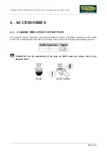
Страница 45: ...ON The machine can be connected to the CardioTheater by means of the RJ45 connector on the CSafe board The CardioTheater unit must be provided with a power cable having the following pin out RJ45 Connector Signal 5 5 Vdc 7 Ground WARNING for the numbering of the pins on RJ45 connector please refer to the diagram below ...

Страница 46: ...e CSafe board WARNING for the numbering of the pins on RJ45 connector please refer to the diagram below When programming the machine sometimes it is necessary to fit plug into the free RJ 45 port on the back of the display to avoid any type of interference during the operation The wiring diagram of the RJ 45 plug is as follows Programming cable and plug can be ordered using the code R0002534AB ...

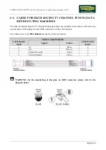
Страница 47: ...ne machine to the other is effected via a special cable which plugs into the RJ45 connectors of the CSafe boards The cable to use code 0WC00644AA must be wired as follows Cable CSafe Periferic CSafe Board RJ45 Signal Colour CSafe Board RJ45 3 Tx White 4 4 Rx Brown 3 7 Digital Ground Green 7 8 Ground Shield Yellow 8 WARNING for the numbering of the pins on RJ45 connector please refer to the diagram...

Страница 48: ... is fitted into any one of the CSafe ports on the machine the corresponding LED should illuminate to indicate the presence of the 5 Vdc supply on the port During the CSafe port test function the plug connects the transmit channel directly to the receive channel thereby producing a positive test outcome if the port is functioning correctly ...

Страница 49: ...HRAIN DVB T PAL B MOROCCO DVB T SECAM B BELGIUM DVB T PAL B G NETHERLANDS DVB T PAL B G BERMUDA DVB T NTSC M NEW ZEALAND DVB T PAL B G BRAZIL ATSC PAL M NIGERIA DVB T BULGARY DVB T SECAM D K NORWAY DVB T PAL B G CANADA ATSC NTSC M OMAN DVB T COLOMBIA ATSC NTSC M PHILIPPINES DVB T NTSC M CYPRUS DVB T PAL B POLAND DVB T PAL D K CZECH REPUBLIC DVB T SECAM PAL D K PORTUGAL DVB T PAL B G DENMARK DVB T ...

Страница 50: ...CARDIO WAVE EXCITE Class Trend Service maintenance manual rev 2 0 Pagina 4 6 LIBYA DVB T ...

Страница 51: ...CARDIO WAVE EXCITE Class Trend Service maintenance manual rev 2 0 Pagina 4 7 Page intentionally left blank ...

Страница 52: ......

Страница 53: ...ot positioned close to sources of heat sources of electromagnetic noise television sets electrical motors antennas high voltage lines household appliances etc or medical equipment 5 To eliminate any interference with the cardio receiver no transmitters should be placed less than 90cm from the display Only for the 500 700 and 700WTV models 6 The mains voltage must match the value specified on the m...

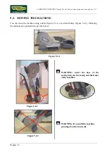
Страница 54: ...the machine using a dolly Figure 5 2 1 or an hand trolley Figure 5 2 2 following the indications reported in the picture below Figure 5 2 1 Figure 5 2 2 WARNING insert the base of the trolley between the casing and the frame of the machine Figure 5 2 3 WARNING Do not tilt the machine pivoting it on the front side ...

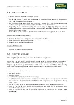
Страница 55: ... a usable antenna signal for radio channel tuning RADIO FM SIGNAL On machines with Digital TV receiver it is possible only the tuning of the digital band and not the analogue one 5 3 1 DIGITAL SIGNAL DVB T Level Higher than 65 dBm 44 dBµV 16 dBmV Quality CH B E R 10 3 Channel Bit Error Rate Or C N Carrier to Noise ratio Modulation type 16 QAM 13 dB Modulation type 64 QAM 23 dB ATSC Level Higher th...

Страница 56: ...dBm 59 dBµV 1 dBmV Quality S N Signal to Noise ratio Higher than 50 dB WARNING If the machine is not connected to a terrestrial antenna or if it is but the antenna signal line is interrupted by devices such as TV distribution units modulators etc the machine will not be able to receive a usable antenna signal for radio channel tuning ...

Страница 57: ... Only for 700WTV model 7 Connect the antenna cable to the socket 5 5 FIRST POWER ON After completing the installation procedure the machine is ready for use On the 500 700 and 700WTV models simply turn the on off switch from position 0 to position 1 while on the 500SP and 700SP models it is necessary to get on the machine and start pedaling On power up the machine performs a self test of the upper...

Страница 58: ...CARDIO WAVE EXCITE Class Trend Service maintenance manual rev 2 0 Pagina 5 6 Page intentionally left blank ...

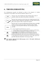
Страница 59: ...e troubleshooting procedure where an ACTION must be carried out It typically contains a description of the ACTION necessary to resolve the problem Therefore after executing the specified ACTION 1 Check whether the problem has been resolved 2 If the problem persists it is recommended to resume the troubleshooting procedure from the point before the action was carried out A circled number such as th...

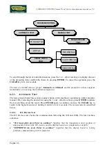
Страница 60: ...e bottom left hand and the bottom right hand corner in sequence as shown in the picture below The machine display will shows a window from where you can access the different configuration menus using the proper password To access the menu type in the password 2411 and press ENTER key to confirm or BACK key to back forward At this point the machine display will shows the different parameters of the...

Страница 61: ...ks the communication on CSafe ports The test can have two outcomes Test Successful This means that the test was completed successfully i e that serial communications on the selected port are correct Error COM1 This means that the outcome of the test was negative The CSafe COM test done on a machine which CSafe port is not plugged with the monitor plug described at chapter 4 of the Service Maintena...

Страница 62: ...s that the outcome of the test was negative The TGS COM test done on machine not provided with the key reader gives a fail outcome 6 1 5 DVT BOARD TEST It s a command that allows to divert the serial communication usually between the Digital TV boardand the CPU board on the external CSafe port This function wich allows to connect an external device to the Digital TV board is not used at the moment...

Страница 63: ... At this point there are two options available Tech Config Troubleshooting Press numeric key to access the menu for configuring technical parameters the machine display will begin showing the current configuration structured as in the diagram below Accessing configuration of 700 models Simultaneously press the keys 369 for 700 LED models whereas on 700 Wellness TV models the keys 0369 must be pres...

Страница 64: ...ST The tests grouped under this section conduct checks on the machine s operation in a fully automatic manner After selecting the desired test using the and effort level keys press ENTER to initiate the test and then await the result Press ENTER again to continue and use the CLEAR key to return to the higher menu level holding it down for a few seconds The various tests are described below 6 2 1 1...

Страница 65: ...tive the message will specify COM1 in the case of the CSafe COM test COM2 in the case of communications with the low kit or COM3 in the case of the TGS COM test The TGS COM test done on machine not provided with the key reader gives a fail outcome The same if the CSafe COM test is done on a machine which CSafe port is not plugged with the monitor plug described at paragraph Errore L origine riferi...

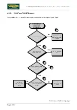
Страница 66: ...e upper assembly 6 3 1 500 AND 700 MODELS Does the wall outlet supply the correct voltage Is the mains lead OK Are the LEDs on the Display board lit on Plug the machine into a working electrical outlet Replace the mains lead Replace the Display board THE DISPLAY DOES NOT ILLUMINATE NO YES NO YES NO YES A 1 Are the fuses OK Replace the fuses YES NO Continued on the following page ...

Страница 67: ...robes across pins 3 and 1 of CN4 connectors on the Brake Board The measured value should be approximately 220 VAC or 110 VAC depending on the mains voltage 3 Slightly lift up the fast on on the machine power entry module Place the tester probes across the live and neutral pins on the same connector The measured value should be approximately 220 VAC or 110 VAC depending on the mains voltage 4 Using...

Страница 68: ...he LEDs on the Display board lit on Are the LEDs on the Brake board lit on while pedaling Correct operation after 30 seconds without pedaling the machine switches off Replace the Display board THE DISPLAY DOES NOT ILLUMINATE NO YES NO YES NO YES 2 1 B Replace the CU67 and or CU62 cables Are the DC voltages at the output of the brake board correct NO 3 Replace the Brake board YES 4 Continued on the...

Страница 69: ... t about 12Vdc recharge the battery for 8 hour with an external power pack without using the machine 2 Check the LEDs 1 and 2 green and yellow of the Display Board are correctly lit on 3 Check if the LEDs 1 and 2 green and yellow of the Brake Board are correctly lighting on as described in paragraph 3 1 7 Brake board 4 Using a tester check that all the output voltages on connector CN1 of the Brake...

Страница 70: ...Does the wall outlet supply the correct voltage Is the mains lead OK Are the LED on the Display board lit on Plug the machine into a working electrical outlet Replace the mains lead THE DISPLAY DOES NOT ILLUMINATE NO YES NO YES YES NO B 1 Are the fuses OK Replace the f uses YES NO Continued on the following page ...

Страница 71: ... 2 Start exercising by choosing Quick Start mode and press on the Touch Sensors Is the resistance change Do you hear beep sound NO Replace CPU board YES Replace the LCD inverter Does the problem persists YES Replace LCD A NO Defective LCD inveter Continued on the following page ...

Страница 72: ... output of the Brake board correct NO Replace the Brake board 5 B Are the voltages on the patch connectors 1 and 3 are correct NO Replace CU67 and or CU62 cables Are the voltages at the input of the Digital TV board correct NO Replace CU169 cable YES YES YES 6 7 Are the voltages at the input of the CPU board correct YES Replace CPUboard NO Replace CU169 cable 8 4 Is the voltage at the output of th...

Страница 73: ... same connector The measured value should be approximately 220 VAC or 110 VAC depending on the mains voltage 5 Using a tester check that all the output voltages on connector CN1 of the Brake board The measured value should be 12 Vdc between pins 6 2 5 Vdc between pins 7 3 6 As for step 5 but on patch connectors 1 and 3 of CU67 and CU62 cables 7 Place the tester probes across pins 1 and 2 of J1 con...

Страница 74: ...reen 2 Replace the Touch Screen Does it work correctly NO YES 1 Follow the procedure step by step to correctly diagnose the problem Take particular care with the checks highlighted by circled numbers which are described in detail below 1 It s recommended to upgrade the HW and SW of machine display to the last version due to the steady work on the product for its improvement Please refers to the pr...

Страница 75: ...e the CPU board NO Follow the procedure step by step to correctly diagnose the problem Take particular care with the checks highlighted by circled numbers which are described in detail below 1 Carry out the configuration procedure as detailed at paragraph 9 5 6 TV Standard If you replace Display board Brake board check that its SW version is updated otherwise install the last version The TV and RA...

Страница 76: ...antenna signal ATTENTION ONLY FOR JAPAN Before to carry out the following troubleshooting check that the B CAS card is correctly inserted on the TV Digital Board NO TV PICTURE Check if the antenna cable is properly connected Connect the cable NO 1 On the other machines you see the TV Check the antenna signal NO Connect the machines at one antenna soket sure working Replace the antenna soket NO A Y...

Страница 77: ...e Working Replace the Digital TV board and or the CPU board NO CU160 cable def ective Check the conditions of antenna cable It is CU 198 ok Replace the CU 198 cable NO A Is the TV standard correctly conf igured Conf igure the TV standard parameter NO 2 YES 3 Check the Antenna signal 4 YES YES YES YES ...

Страница 78: ...ard 3 Check that the antenna signal matches with the minimal requested specifications detailed at paragraph 5 3 Recommended antenna signal requirement 4 Check the state of wear of the antenna cable and that it properly works If you replace Display board Brake board check that its SW version is updated otherwise install the last version The TV and RADIO channels is located in the Digital TV in the ...

Страница 79: ...erface is installed check that the parameter 9 3 17 Radio is correctly set It is now possible only the tuning of the digital band and not more the analogue one 1 Is the TV channel sound OK Replace the CPU board Does it work correctly Perf orm the Audio does not work procedure Def ective CPU board NO YES THE RADIO DOES NOT PLAY YES Check if the antenna signal is good NO Is the tuner connected to a ...

Страница 80: ... the minimal requested specifications detailed at paragraph 5 3 Recommended antenna signal requirement If you replace Display board Brake board check that its SW version is updated otherwise install the last version The TV and RADIO channels is located in the Digital TV in the CPU Board and must necessarily be present This means that when even one of the two boards will be replaced should be re st...

Страница 81: ...files uploaded on the iPod Check the audio connection system NO Replace the Docking station board 2 3 YES Check the CU167 cable connection Is the iPod detected by the machine OK YES Is the voltage atthe inputofthe docking station correct Replace the docking station board YES 5 NO 6 NO A Update the iPod SWversion Has been the device enabled fromthe proper function in the user menu Enable the iPod N...

Страница 82: ...ard correct Replace the AUX board YES 8 Is the voltage at the output of the Digital TV board correct Replace CU166 cable YES 9 NO A Is the voltage at the output of the AUX board correct Replace CU167 cable YES NO 11 Is the v oltage on the patch connector correct 10 Replace Digital TV board NO Replace CU169 cable NO YES ...

Страница 83: ...connection option in the user menu 6 The CU167 cable has identical connectors on either end then it can sometimes be connected the wrong way round Check that the connector marked with a blue sign is connected on the AUX connectors board 7 Place the tester probes across pins 8 9 of the connector on the docking station board where the CU167 cable is connected The measured value should be 5 Vdc 8 As ...

Страница 84: ... displayed by a massage and stored in the Errors Log section To reinstate communications between the lower and upper assemblies 1 Check that cables CU69 and CU63 are correct using the Test Box Excite and replace if necessary 2 Try replacing the brake board and the display board in turn and check whether the communication works If you replace Display board Brake board check that its SW version is u...

Страница 85: ...ective Does the brake board supply tension at the brake THERE IS NO RESISTANCE Are the Watt and SPM values shown on the display different f rom zero NO YES 1 Carry out the The speed signal is incorrect troubleshooting procedure Replace the brake board YES Does the input of brake receive tension from the brake NO Replace the brake YES Replace CU71 cable NO 3 YES Is the resistance on the Brake windi...

Страница 86: ...w 1 Place the tester probes across pins 1 2 of the connector CN2 on the brake board and exercise at a speed of 60 RPM You should measure a Vdc which increases according to the exercise level 2 As for step 1 but across the two fast on at the input of the brake 3 As for step 1 but with everything reconnected and across the brake winding If you replace Display board Brake board check that its SW vers...

Страница 87: ...surement is incorrect the brake board is defective the brake is defective Are the mechanics of the machine in good condition Does the brake board output the correct current to the brake winding Replace the brake board NO Replace the Brake winding YES THE RESISTANCE IS INCORRECT 2 Repair the faulty mechanical parts NO Carry out the Speed signal is Incorrect troubleshooting procedure 3 Carry out the...

Страница 88: ...Setting procedure as detailed at paragraph 9 5 5 Standard settings 2 Check that the mechanical system consisting of the pedals belt and brake moves smoothly and without higher than normal friction or resistance 3 Measure the voltage supplied by the brake board to the winding In Quick Start mode select the effort level and check that the value is different from 0 If you replace Display board Brake ...

Страница 89: ...ixed to the flywheel The speed sensor is defective The brake board is defective Does the speed sensor send the correct signal to the brake board 3 Replace the speed sensor generator on SP models NO Replace the Brake board YES THE SPEED SIGNAL IS INCORRECT 1 YES YES Update the brake board SW Is the speed signal correct Def ective SW NO Carry out the Standard Setting procedure 2 ...

Страница 90: ... in Figure 3 2 1 In addition when pedalling at 80 RPM the frequency of the signal should be 136 Hz Self Powered models Check the signal on CU110 cable The measured signal should be that indicated in Figure 3 2 1 In addition when pedalling at 80 RPM the frequency of the signal should be 136 Hz The speed signal can also be observed qualitatively using a multimeter The value should be 0 Vdc when the ...

Страница 91: ...he output to the Display board correct Replace cable CBQ 32 1 2 YES NO YES Replace the display board NO A Is the serial communication link between the display board and the TGS reader OK Replace the TGS reader Is the communication link between the display board and the TGS reader OK TGS reader def ective 3 3 YES NO YES Replace the display board NO A Replace the TGS reader Follow the procedure step...

Страница 92: ...r CN1 of the TGS reader The measured value should be 12 Vdc 2 As for step 1 but across pins 1 and 9 of connector CN8 on the display board 3 Use the serial communications test described at paragraph 6 2 1 3 Serial Ports Test If you replace Display board Brake board check that its SW version is updated otherwise install the last version ...

Страница 93: ... due to a specific SW filter which cut every signal greater than 220 bpm 2 the receiver is not working properly 3 the receiver is not supplied by the display board THERE IS NO HR SIGNAL Is the supply voltage correct at the input to the receiver Is the supply voltage correct at the output of the display board Replace the receiver Replace CU223 cable 2 3 YES NO YES Replace display board NO Carry out...

Страница 94: ...ester probes across pins 1 and 2 of connector HD4 of the receiver The measured value should be 5 Vdc 3 As for step 1 but across pins 1 and 6 of connector CN4 on the display board or CN19 on the CPU board 4 Check the earth connection of the machine using a tester to measure the resistance between the ground pin on the power supply cable and the ground node to which the receiver is connected inside ...

Страница 95: ...s of the problem we recommend to use the functions of Test Box Excite THERE IS NO HR SIGNAL Are the sensors correctly connected to the HS HR receiver Is the voltage at the output of the display board correct Reinstate the connection Replace cable CU223 Replace the display board 2 4 YES NO YES NO Is the voltage at the input to the HS HR receiver correct Replace the HS HR receiver 3 YES NO Verif y t...

Страница 96: ...achine using a tester to measure the resistance between the ground pin on the power supply cable and the ground node to which the receiver is connected inside the display The value must be less than 1 Ohm 2 Check the connections referring to paragraph 2 7 Wiring diagrams 3 Place the tester probes across pins 1 and 2 of connector HD4 of the receiver The measured value should be 5 Vdc 4 As for step ...

Страница 97: ... spaced by the required minimum distance Is the receiv er correctly positioned and are the connecting cables properly routed Are there sources of electromagnetic noise near the receiver Reposition the machines so they are adequately spaced Correct the position of the receiver and the routing of the cables Move the machine away f rom the noise source or attenuate the power of the noise NO YES NO YE...

Страница 98: ... YES NO 5 Follow the procedure step by step to correctly diagnose the problem Take particular care with the checks highlighted by circled numbers which are described in detail below 1 Check the earth connection of the machine using a tester to measure the resistance between the ground pin on the power supply cable and the ground node to which the receiver is connected inside the display The value ...

Страница 99: ...ck for electromagnetic noise near the machine use Test Box Excite as detailed here below You can use one of the following cables ELT 16 0WC00518AB CBQ 28 0WC00390AC or TRM 28 0WC00336AC as connection cable The circuit lights the LED for each heart beat and or disturbance received in this way it is possible to determine whether there is any interference and identify its sources 5 Check the battery ...

Страница 100: ...CARDIO WAVE EXCITE Class Trend Service maintenance manual rev 2 0 Pagina 6 42 Page intentionally left blank ...

Страница 101: ...and unplug the mains lead from the wall outlet Only for 500 2 Back off the 4 screws a using a medium Phillips screwdriver Figure 7 1 2 3 Unplug the connectors as indicated in the figure at left CN9 CN1 CN3 4 Remove the display Figure 7 1 3 5 Back off the 2 screws b using an 8mm hexagonal wrench to remove the rear display support To reassemble the display carry out the above steps in reverse order ...

Страница 102: ... the wall outlet Only for 700 2 Back off the 4 screws a using a medium Phillips screwdriver Figure 7 1 5 3 Unplug the connectors as indicated in the figure at left CN9 CN1 CN6 CN5 CN4 4 Remove the display Figure 7 1 6 5 Back off the 2 screws b using an 8mm Hexagonal wrench to remove the rear display support To reassemble the display carry out the above steps in reverse order ...

Страница 103: ... wall outlet 1 Back off the 4 screws a using a medium Phillips screwdriver Figure 7 1 8 2 Unplug the connectors as indicated in the figure at left CN30 CN26 CN27 CN19 CN20 CN21 CN22 CN25 3 Remove the display Figure 7 1 9 4 Back off the 2 screws b using an 8mm Hexagonal wrench to remove the rear display support To reassemble the display carry out the above steps in reverse order ...

Страница 104: ...oard A The C Safe Board B Figure 7 2 2 Display Board A 1 Disconnect connectors a CN2 of the keyboard and b CN8 of the CSafe board from the Display board 2 Back off the 5 screws c with a medium Phillips screwdriver 3 Remove the circuit board Figure 7 2 3 CSafe Board B 1 Disconnect connector d CN8 of the C Safe from the Display board 2 Remove the circuit board e slipping it off from the top Use agai...

Страница 105: ...Safe Board B Figure 7 2 5 Display Board A 1 Disconnect connectors a CN2 of the keyboard and b CN8 of the CSafe board from the Display board 2 Back off the 5 screws c with a medium Phillips screwdriver 3 Remove the circuit board Figure 7 2 6 CSafe Board B 1 Disconnect connector d CN8 of the C Safe from the Display board 2 Remove the circuit board e slipping it off from the top Use again the hot glu...

Страница 106: ...mble its circuit boards The LCD inverter A The CPU Board B And the circuit boards mounted on the rear display support Digital TV Board Input AUX Board Figure 7 2 8 LCD inverter A 1 Back off the 2 screws a with a medium Phillips screwdriver Figure 7 2 9 2 Remove the covering plate b of the LCD inverter 3 Disconnect the connectors c CN2 CN3 CN5 4 Back off the 2 screws d which fix the board to the di...

Страница 107: ...1 Disconnect the cable s connectors coming from TTL and Touch screen CN3 CN28A on CPU Board On the inverter those direct to the LCD inverter indicated in the figure CN2 CN3 ATTENTION to disconnect the cable coming from the touch screen bend lightly back the protection plate if necessary 2 Back off the 5 screws f which fix the plate with all the Display Boards to the front covering Figure 7 2 12 3 ...

Страница 108: ...0 screws i using a small Phillips screwdriver 8 Remove the touch screen protection plate l Figure 7 2 14 9 Shift touch screen m on one side paying attention to the cable which connect it to the CPU Board Figure 7 2 15 10 Back off the 4 screws n using a small Phillips screwdriver 11 Lift up and remove the LCD ...

Страница 109: ... AUX Board and the antenna cable highlighted in the figure and the power supply cable 3 Back off the 4 screws o with a medium Phillips screwdriver 4 Remove the Digital TV Board Figure 7 2 17 5 Slip off the AUX Input Board p from its housing ATTENTION During the reassembly of the Digital TV Board pay attentions to not squash the cables under it To reassemble the circuit boards carry out the above s...

Страница 110: ...nd detach a corner of the keyboard To assemble a new keyboard with the display on a work bench 1 Remove the backing film from the adhesive 2 Apply the adhesive part starting from the left and working toward the right without bending the keyboard 3 Insert the connector in the special slot on the display and connect it to the display board 4 Remove the protective film ATTENTION When reassembling the...

Страница 111: ...e keyboard To assemble a new keyboard with the display on a work bench 1 Remove the backing film from the adhesive 2 Apply the adhesive part starting from the left and working toward the right without bending the keyboard 3 Insert the connector in the special slot on the display and connect it to the display board 4 Remove the protective film ATTENTION When reassembling the keyboard make sure that...

Страница 112: ...ITE Class Trend Service maintenance manual rev 2 0 Pagina 7 12 7 3 3 700WTV VERSION WELLNESS TV To disassemble the Touch Screen please refer to the Display Board disassembly procedure 7 2 3 700WTV version Wellness TV ...

Страница 113: ...off the machine and unplug the mains lead from the wall outlet 1 Back off the 6 screws a using a medium Phillips screwdriver 2 Lift up the upper casing b Figure 7 4 2 3 Unthread the receiver from its housing with the protection sponge c Figure 7 4 3 4 Remove the protection sponge and remove the cardio receiver d Continued on following page ...

Страница 114: ...l e and the connectors f and g 2 Connect the cables to the receiver as in the figure to side Figure 7 4 5 3 Wrap the receiver again in the sponge h using a cable tie to fix it 4 Reinsert the receiver inside of the home ATTENTION Position the receiver so that the coil is oriented towards the user To reassemble the cardio receiver carry out the above steps in reverse order ...

Страница 115: ...k off the 4 screws b with a 6mm hexagonal wrench During reassembly lock down the screws b using a torque wrench setting of 27Nm 20ft lbf Figure 7 5 3 To disassemble all parts of the handlebar 1 Back off the 2 screws c with a 6mm hexagonal wrench on both side of the machine During reassembly lock down the screws c using a torque wrench setting of 62Nm 45 7ft lbf To reassemble the handlebar carry ou...

Страница 116: ...he mains lead from the wall outlet For each sensor 1 Back off the 2 screws a using a medium Phillips screwdriver Figure 7 6 2 2 Lift up the top sensor 3 Remove the lower sensor 4 To remove the sensors unplug the two faston and the connector b of the touch sensor indicated in the figure To reassemble the sensors carry out the above steps in reverse order ...

Страница 117: ...n both sides of the machine During reassembly insert the longer screws in the position indicated by the arrows 2 Lift up the upper guard b securing it to the upper side of the machine with some adhesive tape or with a cord Figure 7 7 2 3 Back off one of the 2 screw c using a 5mm hexagonal wrench 4 Remove the two front guards Figure 7 7 3 5 Lower both the pedals 6 Back off the 3 screws d using a 5m...

Страница 118: ... top Figure 7 7 5 9 Remove the sweat protection guard e1 if necessary Figure 7 7 6 10 Overturn the machine on one side and back off the 4 nuts f using a 17mm wrench 11 Place the machine in usage position and pull out the rear guard assembly from the top During reassembly lock down the screws f using a torque wrench setting of 27Nm 20ft lbf To reassemble the guards carry out the above steps in reve...

Страница 119: ...Back off the screws b using a 17mm wrench 3 Remove the upper part of the column pulling it out from the top Pay attention to unplug the junction connectors of the cables which goes from the display to the lower electronic Figure 7 8 3 To reassemble the upper column carry out the above steps in reverse order During reassembly lock down the screws a and b using a torque wrench setting of 40Nm 29 5ft...

Страница 120: ...erior guard 1 Back off the 2 screws a with a 8mm wrench to remove the Brake Box and replace if is necessary Figure 7 9 2 2 Back off the screw b using a medium Phillips screwdriver 3 Open the cover plate of the Brake box Figure 7 9 3 4 Unplug the 4 connectors indicated in the figure at left 5 Remove the Brake Box and replace if necessary To reassemble the Brake box carry out the above steps in reve...

Страница 121: ...Service maintenance manual rev 2 0 Pagina 7 21 7 10 DISASSEMBLING THE FOOTBOARDS Figure 7 10 1 1 Back off the 4 nuts a with a 10mm wrench 2 Remove the footboard To reassemble the footboards carry out the above steps in reverse order ...

Страница 122: ...embled in such a way that the belt cam is in the position shown in the figure 2 Lock the cam in place by pushing a wrench or screwdriver behind the belt clamping block and into a hole in the frame behind the cam 3 Unhook the belt latch and pull from the insert on cam as in figure at the side Figure 7 11 2 4 Disconnect the tie rod from the footboard lever belt back off the screw a with a 6mm hexago...

Страница 123: ...l the nut is fully up against the clamping system Lock down the nut using a torque wrench setting of 18Nm 13 3ft lbf If the nut has been moved from its original position check in paragraph 8 6 Tie rod length Figure 7 11 4 7 Disassemble the tie rod fastener from the belt by sliding component e along the belt 8 Then remove the wedge f and the threaded connector g from the belt Figure 7 11 5 To reass...

Страница 124: ...000681 Figure 7 12 1 Carry out the operations described in paragraphs 7 7 Disassembling the guards 1 Back off one of the nuts a it depends from which of the lever has to be disassembled using a 17mm wrench to disconnect the tie rod of the lever from the frame 2 Back off one of the screws b it depends from which of the lever has to be disassembled using a 6mm hexagonal wrench and a 17mm wrench to l...

Страница 125: ...nd the belt clamping block and into a hole in the frame behind the cam Figure 7 12 3 5 Detach the tie rod connected to the belt by the pedal lever backing off the screw c using a 6mm hexagonal wrench and holding nut b in place with a 17mm wrench Figure 7 12 4 6 Back off the ring nut e using a 17mm ring nut spanner and remove the two washer f 7 Remove the lever from the pin on the frame At last che...

Страница 126: ...ot grasp the lever from the pedal itself as this might produce additional play associated with the fixing of the pedal 3 Slowly begin tightening the ring while continuing to move the lever until there is no longer any play on the lever If using a torque wrench lock down with a setting of 15Nm 11 1ft lbf 4 At this point tighten the ring further by another 45 1 8th of a turn although it may feel lik...

Страница 127: ... guards On the lever that you want to remove 1 Lower the footboard so that the cam which is wrapped the strap at the position indicated in figure 2 Lock the cam inserting a wrench behind the clamping strap centring a hole in the frame behind the cam Figure 7 13 2 3 Back off the nut a it depends from which of the lever has to be disassembled with a 17mm wrench to disconnect the tie rod of the lever...

Страница 128: ...osition Figure 7 13 4 5 Back off the fixing lever screw using a ratchet wrench and a 17mm socket wrench and remove the two washers as shown in the figure at the side During the reassembly lock down the screws using a torque wrench setting of 15Nm 11 1ft lbf Figure 7 13 5 6 Remove the lever d from the pin on the frame highlighted in the figure Continued on following page ...

Страница 129: ...ever avoiding to damage the internal bearings use the special pin 0T020901AA 7 Screw completely in the special tool e on the pin frame f Figure 7 13 7 8 Insert the lever d on the pin e moving slowly and paying particular attention to the internal bearings of the lever During the reassembly check the length of the tie rods as detailed at the paragraph 8 6 Tie rod length if they had been removed ...

Страница 130: ...spring a Be careful because the spring might remain slightly loaded exerting pressure on the screw b Figure 7 14 2 3 Back off the screw c using a 3mm hexagonal wrench to remove the screw the washer and the other two components used to fix the spring During reassembly remember to put all the components in the proper order as shown in the figure to side Figure 7 14 3 4 Remove the spring d pulling it...

Страница 131: ...e manual rev 2 0 Pagina 7 31 Figure 7 14 4 To reassemble the spring and the cam carry out the above steps in reverse order The cams used on the two sides of the machine are both the same part so check the proper point of connection for spring and belt ...

Страница 132: ...onnectors a from the winding 2 Unplug the connector circled in the figure at left Figure 7 15 2 3 Back off the 2 screws b using an 17mm wrench supporting the entire brake winding group c to avoid damaging the copper disk 4 Remove the brake winding assembly To reassemble the brake winding carry out the above steps in reverse order After completing the reassembly adjust the position of the winding g...

Страница 133: ...m the frame of the machine 2 On the machine frame mark the position where the secondary shaft is assembled as indicated by the arrows in the example 3 Back off the 4 screws a using a 17mm wrench 4 Back off the screw b using a 17mm wrench sliding down the frame on which the secondary shaft assembly is mounted to slacken the belt tension Figure 7 16 2 5 Back off the screw c using a 6mm hexagonal wre...

Страница 134: ...e 6 screws f using a 4mm hexagonal wrench Take particular care with the copper disk as it bends easily and may then cause problems after reassembly by brushing against the winding block During reassembly lock down the screws f using a torque wrench setting of 6Nm 4 4ft lbf To reassemble the secondary shaft assembly carry out the above steps in reverse order After completing the reassembly carry ou...

Страница 135: ...ck off the two screws g using a 3mm hexagonal wrench 9 Back off the grub screw h using a 2 5mm hexagonal wrench 10 Remove the piece i 11 Remove the secondary shaft assembly from the belt and place it on a work bench Figure 7 16 4 12 Remove the stator l from the flywheel m pulling out one from the other Continued on following page ...

Страница 136: ...nds easily and may then cause problems after reassembly by brushing against the winding block During reassembly lock down the screws f using a torque wrench setting of 6Nm To reassemble the secondary shaft assembly carry out the above steps in reverse order After completing the reassembly carry out the adjustment procedure described in paragraph 8 1 Belt tension and 8 4 Align the belt connecting t...

Страница 137: ...to slacken the tension of the belts Figure 7 17 2 3 Back off the 4 screws a using a 17mm wrench 4 On the machine frame mark the position where the secondary shaft is assembled as indicated by the arrows in the example 5 Back off the screw b using a 17mm wrench to slacken the tension of the belt that connects the primary shaft to the secondary Figure 7 17 3 On both side of the machine 6 Derail the ...

Страница 138: ...free wheel During reassembly take care to fit the free wheels in the correct direction so that they are able to rotate freely in the direction indicated by the arrows Figure 7 17 6 13 Back off the 4 screws h locking down the nuts on the opposite side of the pulley using a 13mm wrench 14 Remove the pulley from the shaft To reassemble the primary shaft assembly carry out the above steps in reverse o...

Страница 139: ...LT BETWEEN PRIMARY AN D SECONDARY SHAFT To disassemble the connection belt between the primary and secondary shaft it needs to remove the primary shaft assembly and the secondary shaft assembly as detailed in paragraph 7 16 Disassembling the secondary shaft assembly and 7 17 Disassembling the primary shaft assembly ...

Страница 140: ...Back off the 2 screws a using a 4mm hexagonal wrench 2 Remove the speed sensor and its support To remove only the sensor 1 Cut the cable tie b 2 Unplug the faston indicated in the figure 3 Back off the 2 screws c using a small Phillips screwdriver and remove sensor To reassemble the speed sensor carry out the above steps in reverse order After completing the reassembly adjust the position of the s...

Страница 141: ...rn the machine over on one side 1 Back off the screws a using a medium Phillips screwdriver 2 Remove the power entry module plate covering b Figure 7 20 2 3 Back off the two screws c using a medium Phillips screwdriver and remove the power entry module 4 Disconnect the cable d from the power entry module 5 Remove the power entry module ...

Страница 142: ... the platform raised off the ground 2 Back off the 5 screws a using a medium Phillips screwdriver and remove the 2 covering plates b 3 Remove the front platform pulling it out from the top Pay attention during reassembly not to crush the cables which goes to the power entry module Figure 7 21 2 To disassemble the bottom guard of the rear platform 1 Turn the machine over on one side 2 Back off the ...

Страница 143: ...22 SMONTAGGIO BATTERIA Figure 7 22 1 Carry out the operations described in paragraph 7 7 Disassembling the guards 1 Remove the 2 cable ties a 2 Unplug the 2 fastons b and remove the battery replace if is necessary To reassemble the battery carry out the above steps in reverse order ...

Страница 144: ...CARDIO WAVE EXCITE Class Trend Service maintenance manual rev 2 0 Pagina 7 44 Page intentionally left blank ...

Страница 145: ...emoving the front guard 1 Back off the screws a and adjust the tension of the belt by acting on the screw b The correct belt tension is 190 Hz If a new belt is used after having tensioned it according the above procedure it is recommended to exercise for a minute in order to pull the belt Then check again the tension value 2 At the end of the tensioning procedure remember to lock the screws a back...

Страница 146: ...8 2 8 2 SPEED SENSOR POSITION Figure 8 2 1 Carry out the operations described in paragraph 7 7 Disassembling the guards 1 Back off the 2 screws a and shift the speed sensor support to the side so that it is 0 7mm from the screws on the copper disk 2 Lock the screws back down ...

Страница 147: ... 3 BRAKE WINDING POSITION Figure 8 3 1 Carry out the operations described in paragraph 7 7 Disassembling the guards 1 Back off the 2 screws a and position the brake winding support b so that it is centred on the copper disk using a 1mm thickness gauge 2 Lock the screws back down ...

Страница 148: ...igure 8 4 1 Carry out the operations described in paragraph 7 7 Disassembling the guards for disassembling the front guard 1 Check that the pulley on the primary shaft is aligned with the sprocket on the secondary shaft using a straight reference rod and adjust the bridge bearings if needed moving them sideways inside the slots on the frame ...

Страница 149: ...with a 13mm wrench for adjusting the distance between the footboards in stand by position look again Figure 8 5 2 3 Rotate the shock absorber in clock wise or counter clock wise until the distance between the two pedals is 50mm forcing them in its upper position Put some drops of Loctite on the counter nut a to fix it ATTENTION check that the shock absorber even in its two extreme positions i e wi...

Страница 150: ...ntenance manual rev 2 0 Pagina 8 6 8 6 TIE ROD LENGTH Adjust the length of the tie rods according to the data for each of them in the following figures Figure 8 6 1 Figure 8 6 2 Figure 8 6 3 Figure 8 6 4 Figure 8 6 5 Continued on following page ...

Страница 151: ...igure 8 6 7 During reassembly procedure lock down the ball joints using a torque wrench setting of 22Nm 16 2ft lbf excepting the ones in Figure 8 6 4 and Figure 8 6 7 which need a tightening torque of 25Nm 18 4 ft lbf Refer to the Spare Parts Catalogue as regards the codes of rods and levers ...

Страница 152: ...CHINE IS NOT FLAT This problem may be due to the positioning of the machine on a not flat surface To resolve this problem is necessary to act on foot adjustment Figure 8 7 1 1 Screw the foot a in or out until the frame is in a stable position 2 Adjustment made to tighten the counter nut b ...

Страница 153: ...ASSWORD To access the procedure type in the password 2406 and press ENTER to confirm To enter the password increase or decrease the displayed value using the and keys or use the GOAL keys to scroll through and modify the individual digits At this point the machine display begins showing the current configuration structured as in the diagram below USER MENU Language MAX time Cooldown time Distance ...

Страница 154: ...y shows the current setting UNITS xxx Press the GOAL keys to select the desired unit of measurement from the options listed in the table below UNITS KG default POUNDS Press ENTER to confirm the operation use the or effort level keys to move to the next or preceding parameter 9 1 3 MAXIMUM EXERCISE TIME It is possible to set a maximum duration for each exercise ranging from 1 to 9999 minutes To cha...

Страница 155: ...LDOWN TIME xxx Press the ENTER key to change the value The current parameter value starts to blink on the display use the and keys to increase or decrease the value or use the GOAL keys to scroll through and modify the individual digits Press ENTER to confirm the operation use the or effort level keys to move to the next or preceding parameter The default value of this parameter is 60 If you are e...

Страница 156: ...the display shows the current duration DEFAULT DURATION MIN xxx Press the ENTER key to change the parameter The current parameter value starts to blink on the display use the and keys to increase or decrease the value or use the GOAL keys to scroll through and modify the individual digits Press ENTER to confirm the operation use the or effort level keys to move to the next or preceding parameter T...

Страница 157: ...lt value of this parameter is 10 9 1 11 ENABLE TGS It is possible to enable or disable the use of the TGS reader To change the selection when the display shows the current setting TGS xxx Press the GOAL keys to select the desired option out of those listed in the table below TGS ENABLED default DISABLED Press ENTER to confirm the operation use the or effort level keys to move to the next or preced...

Страница 158: ...s possible to reset the user menu parameters to their default values To select the function when the display shows DEFAULT CONFIG Press ENTER to confirm the operation use the or effort level keys to move to the next or preceding parameter If the ENTER key is pressed the display will show CONFIRM press ENTER to confirm or cancel by pressing the CLEAR key for a few seconds 9 1 15 FORMAT P P KEY This...

Страница 159: ...ss TV models the keys 0369 must be pressed one after the other The following prompt appears on the display ENTER PASSWORD To access the procedure type in the password 2406 and press ENTER to confirm At this point the machine display begins showing the current configuration structured as in the diagram below USER MENU Language Pause time MAX time Distance TGS Keys HR Edit Messages Default config Fo...

Страница 160: ...ows the current setting DISTANCE xxx Press the GOAL keys to select the desired unit of measurement from the options listed in the table below DISTANCE KM default MLS Press ENTER to confirm the operation use the or effort level keys to move to the next or preceding parameter 9 2 3 MAXIMUM EXCERCISE TIME It is possible to set a maximum duration for the exercise in minutes with a value ranging from 1...

Страница 161: ...To change the setting when the display shows the currently selected maximum time COOLDOWN TIME xxx Press the ENTER key to change the value The current parameter value starts to blink on the display use the and keys to increase or decrease the value or use the GOAL keys to scroll through and modify the individual digits Press ENTER to confirm the operation use the or effort level keys to move to th...

Страница 162: ...during a constant heart rate exercise To change the selection when the display shows the current setting HR xxx Press the GOAL number keys to select the desired option out of those listed in the table below HR MODIFIABLE default NOT MODIFIABLE Press ENTER to confirm the operation use the or effort level keys to move to the next or preceding parameter 9 2 9 ENABLE CUSTOM MESSAGES It is possible to ...

Страница 163: ...fined custom standby messages when the LED display is showing the current selection CHANGE MESS LANGUAGE Press ENTER to confirm the operation use the or effort level keys to move to the next or preceding parameter 9 2 12 ENABLE MULTI LANGUAGE MODE The machine can be configured to allow selection of the language at each session To change the selection when the display shows the current setting LANG...

Страница 164: ...ction when the display shows FORMAT P P press ENTER to confirm or cancel by pressing the CLEAR key for a few seconds At the end of the configuration procedure hold down the CLEAR key for a few seconds to exit The CLEAR key can be pressed at any time to interrupt the procedure and revert to standby mode 9 2 15 SN This parameter shows the serial number of the machine SN xxxx ...

Страница 165: ...you can access the different configuration menus using the proper password To access the menu type in the password 2406 and press ENTER key to confirm or BACK key to back forward At this point the machine display will shows the different parameters of the menu collected in different pages which can be scrolled with the FORWARD and BACK keys To exit the configuration press HOME key Pressing HOME in...

Страница 166: ...bsequently displayed by the machine will be in the chosen language To change the selection select the desired option among the ones in the list directly touching on the Touch Screen Press HOME to confirm and save FORWARD or BACK to scroll the pages 9 3 3 MEASURE It is possible to choose between EUROPEAN units kg and km or IMPERIAL units pounds and miles To change the selection select the desired o...

Страница 167: ...o confirm and save FORWARD or BACK to scroll the pages 9 3 6 MAXIMUM EXCERCISE TIME It is possible to set a maximum duration for the exercise in minutes with a value ranging from 1 to 9999 To change the setting press the MODIFY key and insert the value using the numeric keyboard Press ENTER key to confirm or BACK key to back forward The default value of this parameter is 9999 Press HOME to confirm...

Страница 168: ...e operation use the or effort level keys to move to the next or preceding parameter The default value of this parameter is 60 If you are exercising with a TGS key the cooldown will be stopped if you extract the key 9 3 9 TOP EXERCISE PROGRAMS FOR YOU SHORTCUT It is possible to choose 2 extra training programs from the list of those available which will be displayed in the main page with the fixed ...

Страница 169: ...on the Touch Screen STANDBY TV ON default TV OFF Press HOME to confirm and save FORWARD or BACK to scroll the pages 9 3 12 LANGUAGE The machine can be configured to allow selection of the language at each session To change the selection select the desired option among the ones in the list directly touching on the Touch Screen LANGUAGE FIXED default OPTIONAL Press HOME to confirm and save FORWARD o...

Страница 170: ...using the numeric keyboard Press ENTER key to confirm or BACK key to back forward The default value of this parameter is 10 Press HOME to confirm and save FORWARD or BACK to scroll the pages 9 3 16 DISPLAY IN THE WORKOUT It is possible to configure the size of the exercise data during the workout To change the selection select the desired option among the ones in the list directly touching on the ...

Страница 171: ...TION OPTION DOCKING STATION default NOTHING Press HOME to confirm and save FORWARD or BACK to scroll the pages 9 3 19 STANDBY CHANNEL It is possible to set the channel which is displayed on the TV when the TV is in standby To change the setting press the MODIFY key and insert the value using the numeric keyboard Press ENTER key to confirm or BACK key to back forward Press HOME to confirm and save ...

Страница 172: ...l digits At this point there are two options available Tech Config Troubleshooting Press numeric key to access the menu for configuring technical parameters the machine display will begin showing the current configuration structured as in the diagram below 4 Accessing configuration of 700 models Simultaneously press the keys 369 for 700 LED models whereas on 700 Wellness TV models the keys 0369 mu...

Страница 173: ...ress the or effort level keys to display the next or the preceding item To modify a parameter value it is necessary to press the ENTER key when the current parameter value starts to blink press the CLEAR key to erase the current value and then use the number keys to enter the desired new value Save the changes made by pressing the ENTER key To cancel the operation press the CLEAR key for a few sec...

Страница 174: ...s this function also includes the 3 sub functions described below 9 4 1 1 Read from low kit To read the parameter values from the low kit memory and view them on the display scroll using the keys until the display shows READ FROM LOW KIT press ENTER to read the errors from the low kit and return to the upper menu level by pressing CLEAR for a few seconds 9 4 1 2 Write to low kit To write the value...

Страница 175: ...the Write to low kit function 9 4 1 4 Table of configuration parameters Parameter Description Defaultvalues Par 01 Transmission ratio 4248 Par 02 Speed ratio integer part 400 Par 03 Minimum braking current standby pos mA 500 Par 04 Maximum continuous power W 200 Par 05 Machine torque correction coefficient constant torque 85 Par 06 User friction torque 10 Par 07 Maximum coil temperature C 125 Par ...

Страница 176: ...llows OPERATING DATA Life Kit H Life Brake WRITE TO LOW KIT READ FROM LOW KIT Life Kit L Tot Km KJ In addition to the machine usage data this function also includes the 2 sub functions described below 9 4 2 1 Read from low kit To read the parameter values from the low kit memory and view them on the display scroll using the keys until the display shows READ FROM LOW KIT press ENTER to read the err...

Страница 177: ...he machine is switched off any data modified after the last memory update will be lost MESSAGE ON DISPLAY DESCRIPTION Life Brake Minutes x 10 of operation of the brake Life Kit H Minutes x 10 of operation of the upper assembly Life Kit L Minutes x 10 of operation of the lower assembly Tot Km Total km traveled KJ Total KJ during exercise By selecting one of the items in the above table it is possib...

Страница 178: ...ncludes the 3 sub functions described below 9 4 3 1 Read from low kit To read the errors stored in low kit memory and view them on the display scroll using the keys until the display shows READ FROM LOW KIT press ENTER to read the errors from the low kit and return to the upper menu level by pressing CLEAR for a few seconds 9 4 3 2 Reset Errors To clear the error history in both the low and high k...

Страница 179: ...3 4 View Errors For every error generated by the machine the error history log records the information in the table below Counter Error code Current when the error occurred Distance in km when the error occurred The correspondence between error codes and descriptions is given in the table below Error Code Description 1 OVERHEATING this condition occurs when the temperature detected by the sensor o...

Страница 180: ...s or return to the upper menu level by pressing CLEAR for a few seconds This function does not alter the language and the TV standard setting 9 4 5 LOW KIT MENU This function directly accesses the firmware of the brake board To access this menu when the display shows LOW KIT MENU press ENTER This function is structured as follows LOW KIT MENU Low Kit Version Low Kit fault code 9 4 5 1 Low kit vers...

Страница 181: ...IT VERSION This function displays the SW version of the display To do this when the display shows HIGH KIT VERSION press ENTER the message that identifies the SW version will appear 9 4 7 BOOT VERSION This function displays the BOOT version To do this when the display shows BOOT VERSION press ENTER to display the message which identifies the BOOT version 9 4 8 KEY READER VERSION This function disp...

Страница 182: ...ou can access the different configuration menus using the proper password To access the menu type in the password 2501 and press ENTER key to confirm or BACK key to back forward At this point the machine display will shows the different parameters of the menu collected in different pages which can be scrolled with the FORWARD and BACK keys To exit the configuration press HOME key Pressing HOME in ...

Страница 183: ...u when the display shows In addition to the 13 configuration parameters this function also includes the 3 sub functions described below 9 5 1 1 Read from low kit To read the parameter values from the low kit memory and view them on the display press READ FROM LOW KIT key 9 5 1 2 Write to low kit To write the values of the currently displayed parameters to the low kit press WRITE TO LOW KIT key 9 5...

Страница 184: ...oad them in the low kit using the Write to low kit function Parameter Description Default values Par 01 Transmission ratio 4248 Par 02 Speed ratio integer part 400 Par 03 Minimum braking current standby pos mA 500 Par 04 Maximum continuous power W 200 Par 05 Machine torque correction coefficient constant torque 85 Par 06 User friction torque 10 Par 07 Maximum coil temperature C 125 Par 08 Minimum ...

Страница 185: ...splay the parameter values you need to load them from the low kit using the Read from low kit function MESSAGE ON DISPLAY DESCRIPTION Life Brake Minutes x 10 of operation of the brake Life Kit H Minutes x 10 of operation of the upper assembly Life Kit L Minutes x 10 of operation of the lower assembly Tot Km Total km traveled KJ Total KJ during exercise By pressing the RESET key on the side of the ...

Страница 186: ... key on the side of the value To correctly display the parameter values you need to load them from the low kit using the Read from low kit function For every error generated by the machine the error history log records the information in the table below Counter Error code Current when the error occurred Distance in km when the error occurred The correspondence between error codes and descriptions ...

Страница 187: ...l TV board SW version the iPod docking station SW version Press HOME to confirm and save FORWARD or BACK to scroll the pages 9 5 5 STANDARD SETTINGS This function allows you to reset the usage data of the machine and simultaneously set the default values of the parameters of the inverter To make the restoration of values press the STANDARD SETTINGS button This function does not change the language...

Страница 188: ...BULGARY DVB T SECAM D K NORWAY DVB T PAL B G CANADA ATSC NTSC M OMAN DVB T COLOMBIA ATSC NTSC M PHILIPPINES DVB T NTSC M CYPRUS DVB T PAL B POLAND DVB T PAL D K CZECH REPUBLIC DVB T SECAM PAL D K PORTUGAL DVB T PAL B G DENMARK DVB T PAL B P R CHINA DVB T PAL D K EGYPT DVB T SECAM B QATAR DVB T FAROE ISLANDS DVB T PAL B ROMANIA DVB T PAL G FINLAND DVB T PAL B G RUSSIA DVB T SECAM D K FRANCE DVB T S...

Страница 189: ...l shows a window from where you can access the different configuration menus using the proper password To access the menu type in the password 2407 and press ENTER key to confirm or BACK key to back forward At this point the partial screen TV is displayed on the machine display as shown in the picture below To permanently save the changes which are going to be made in this page press SAVE IN EEPRO...

Страница 190: ...It is possible to search TV channels on the digital or on the analogue band by pressing on the proper buttons or The default TV standard is the one set at paragraph 9 5 6 TV Standard of the service menu It is anyway possible to store channels transmitted with different TV standard changing this parameter using keys and in the proper menu ...

Страница 191: ...bers in column 2 to scroll through the pages with the numbers and names associated to the channels 4 Once you have found a channel to memorise select it in column 1 then press the number that you want to associate it with in column 2 If a channel has already been memorised under that number the old channel will be overwritten with the new one 5 Repeat the procedure above for each channel you want ...

Страница 192: ...visualized in column 1 it will be displayed then press the number that you want to associate it with in column 2 5 An alphanumeric keypad is displayed to associate a name to the memorised channel 6 Press the ENTER key the keypad will disappear and the name will be displayed next to the number If a channel has already been memorised under that number the old channel will be overwritten with the new...

Страница 193: ...NTS The keys in the figure at left can perform certain adjustments on the Wellness TV In particular it is possible to Increase or reduce the brightness of the LCD Increase or reduce the contrast of the LCD Then 1 Press the SAVE IN EEPROM key to permanently save the configuration 2 Exit with the HOME key ...

Страница 194: ... will shows a window from where you can access the different configuration menus using the proper password To access the menu type in the password 2408 and press ENTER key to confirm or BACK key to back forward At this point the partial screen TV is displayed on the machine display as shown in the picture below To permanently save the changes which are going to be made in this page press SAVE IN E...

Страница 195: ...CARDIO WAVE EXCITE Class Trend Service maintenance manual rev 2 0 Page 9 43 Press YES to save the changes permanently or NO to continue ...

Страница 196: ... channels in column 1 to scroll through the pages with the channels found during the search while use the keys under the list of numbers in column 2 to scroll through the pages with the numbers and names associated to the channels 4 Once you have found a channel to memorise select it in column 1 then press the number that you want to associate it with in column 2 If a channel has already been memo...

Страница 197: ...e to be transferred 2 Insert the TGS key into the reader on the machine 3 Press the SAVE IN TGS button this will cause all the channel configuration data to be saved to the key Up to 45 channels can be memorised in the TGS key if there are more channels to be memorised a message indicates the number of TGS keys required The TGS keys must be inserted one at the time as requested by the messages unt...

Страница 198: ...proper cable described at paragraph 4 3 Cable for exchanging TV channel tuning data between two machines 2 On both machines enter the configuration menu of the channels that need to be tuned 3 Press the READ FROM TGS on the machine to be tuned the channels appears on the machine the written WAITING move on the machine from which you want to transfer channels and press the SAVE IN TGS button on the...

Страница 199: ... in standby mode by pressing the top right hand the bottom left hand and the bottom right hand corner in sequence as shown in the picture below The machine display will shows a window from where you can access the different configuration menus using the proper password To access the menu type in the password 2409 and press ENTER key to confirm or BACK key to back forward ...

Страница 200: ...CARDIO WAVE EXCITE Class Trend Service maintenance manual rev 2 0 Pagina 9 48 At this point the following screenshot appears on the display ...

Страница 201: ...was correctly carried out or Calibration incomplete if the procedure was not completed properly after which the machine reverts to standby mode During the machine power up sequence while the message showing the installed software version is scrolling pressing any point on the touch screen for more than 6 seconds will automatically invoke the calibration procedure as soon as the software version di...

Страница 202: ...CARDIO WAVE EXCITE Class Trend Service maintenance manual rev 2 0 Pagina 9 50 Page intentionally left blank ...

Страница 203: ...and 60601 1 2 electrical testing of each device manufactured according to the provisions of the aforementioned standards training of technical staff who perform technical service use of checked and tested original Technogym spare parts for all service operations 10 1 ELECTRICAL SAFETY TEST Based on the risk analysis carried out by the After Sale department regarding installation and technical serv...

Страница 204: ...CARDIO WAVE EXCITE Class Trend Service maintenance manual rev 2 0 Pagina 10 2 First of all check the resistance on the tester probes is approximately 0Ω ...

Страница 205: ...t level 10 2 2 CHECKING THE ASSEMBLY OF THE GUARDS Check the assembly of the machine guards making sure that They are all in place and correctly secured so that no parts of the machine are left exposed that may cause injury to the user 10 3 START UP CHECK Following installation and after every technical intervention on the machine plug it into a power outlet set the power switch to ON On power up ...

Страница 206: ...N must be guaranteed as traceable The list of these critical components is shown in the table below CODICE COMPONENTE R0004473AB Brake board 0WR00503AB Solenoid assembly W0003767AA Display board 700 0WQ00060AA C Safe board 0WR00633AA Salutron 8500 receiver W0003594AC Schurter socket Display program SW version Brake board program SW version If a critical component listed in this table is replaced d...

Страница 207: ...hs describe the recommended procedures 11 1 DAILY MAINTENANCE OPERATIONS These operations can be carried out by the machine owner and do not require any special skills The daily machine maintenance consists of simple external cleaning for the purposes of general hygiene For the daily maintenance of the machine proceed as follows 11 1 1 SETTING UP THE OPERATION 1 Turn off the machine by placing the...

Страница 208: ...re length and If any anomalies are found call in the authorized Technogym Technical Service 11 2 3 CHECKING THE AMOUNT OF PLAY ON THE BALL JOINTS 1 Check the amount of play on the ball joints If any anomalies are found call in the authorized Technogym Technical Service 11 2 4 CHECKING THE OPERATION OF THE CARDIOTESTER RECEIVER 1 Using a separate heart rate monitor put on the transmitter band and c...

Страница 209: ...ch in position 0 OFF 2 Unplug the mains lead from the wall outlet 11 3 3 CHECKING THE WORKING CONDITIONS 1 Using a multimeter check that the machine earth node is correctly connected to earth 11 3 4 CHECKING THE WEAR OF RUBBER PARTS 1 Check the state of wear of the rubber components Replace if there are evident signs of wear 11 3 5 CHECKING THE BELTS 1 Check the state of wear of the belts using th...

Страница 210: ...NG AND CONNECTIONS 1 Check the condition of all the cables External conditions Possible rusting of the connectors Electrical continuity of the individual wires Isolation of the individual wires toward ground Repair and or replace any non conforming wires 2 Check the condition of the fuses using a tester ...

Страница 211: ...art of the display panel The PC can only update the FLASH EPROM during machine power up before the self test sequence begins After the Display SW update it is necessary to restore all the parameters to the default values following the detailed instructions provided in paragraph 9 2 13 Resetting parameters to default values After the lower electronic SW update it is necessary to restore all the par...

Страница 212: ...iver 7mm wrench 10mm wrench 13mm wrench 17mm wrench 19mm wrench 3mm hexagonal wrench 4mm hexagonal wrench 5mm hexagonal wrench 6mm hexagonal wrench 8mm hexagonal wrench Socket wrench Snap ring pliers You can order a complete set of hexagonal wrenches consisting of 7 pieces 2 2 5 3 4 5 6 and 8 mm The code to be used is R0003677AA PC equipped with Service Excite Loader Serial communication cables fo...

Страница 213: ......

Страница 214: ...0SM00386AA IT TECHNOGYM S p A Via G Perticari 20 47035 Gambettola FC ITALIA Tel 39 0547 650638 Fax 39 0547 650150 e mail service technogym com ...

Отзывы: