3
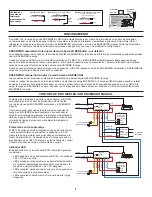
BI-LEVEL CONTROL WITH MANUAL ON
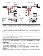
The diagram to the right shows how to configure BZ-150s to
provide bi-level lighting control with both Automatic ON
and Manual ON features.
As shown, upon occupancy detection load A turns ON
automatically. To turn ON load B the user must press momentary
switch B. Both loads turn OFF automatically when the sensor
time delay expires, or manually using switch A and B.
Over Current Protection
The BZ-150 contains built-in short circuit and thermal protection
circuitry that shuts down the +24VDC output (low voltage
red wire) to prevent permanent damage to the power pack.
Removing the excess load from the output restores the BZ-150
to proper operation. Connect the excess load to another power
pack.
LED Indicator
The LED on the reverse side of the BZ-150 indicates the
following conditions:
• LED OFF: no power to the BZ-150, or the +24VDC output is
shorted.
• LED blinking continuously: current output limit is exceeded
(too many sensors are connected to the power pack);
+24VDC output shut down.
• LED ON, blinks once every 4 or 5 seconds: the relay is
closed (load ON).
• LED ON continuously: the relay is open (load OFF).
TROUBLESHOOTING
The lights came ON automatically after I deliberately turned them OFF for a presentation.
• The BZ-150 is set for the Auto ON Mode and the occupancy sensor time delay expired. The BZ-150 reverted to Auto ON and then
motion was detected.
▸
Consider increasing occupancy sensor sensitivity and/or time delay
▸
Generate more motion during presentations.
The load does not turn ON with occupancy detection.
• Mode Switch is set to Manual ON.
• Hold OFF input is active.
The load does not turn OFF after sensor time delay expires.
• Hold ON input is active.
The load does not respond when I press the momentary switch.
• Check wiring.
The load does not come on automatically although the Mode Switch is set to Auto ON.
• Cycle power to the unit to reset operating mode to Auto ON. Mode Switch location was changed while the power pack was was
powered (line voltage).
The load comes on automatically with occupancy although the Mode Switch is set to Manual ON.
• Cycle power to the unit to reset operating mode to Manual ON. Mode Switch location was changed while the power pack was was
powered (line voltage).
Red
Red
Red
Common
+24VDC
Control Output
Brown
Blac
k
Gray
Orange
Red
Blue
Red
Line
Neutral
Black
White
120VAC
277VAC
Line
Neutral
Black
White
120VAC
277VAC
MANUAL ON
BZ-150
(B)
AUTO ON
BZ-150
(A)
Cap
Cap
Brown
Blac
k
Gray
Orange
Red
Blue
Cap
Cap
Auto
ON
Man
ON
COM
SW1
LVSW-101
Low Voltage
Switch Input
COM
SW1
LVSW-101
Low Voltage
Switch Input
Fixture A
Fixture B
(A)
(B)
Sensor
Ceiling/Wall
24VDC
Any
*To
Additional
Sensor(s)
Auto
ON
Man
ON

