
TROUBLESHOOTING
42
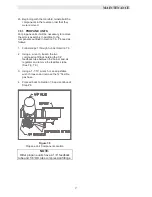
8.3.3 WATER LEVEL CIRCUIT
1. Remove AC power from the unit.
2. Open the control box to expose the wiring
and internal components.
WARNING!
THE WIRES AND COMPONENTS IN THE
CONTROL PANEL USE 120VAC POWER.
DO NOT TOUCH ANY WIRES OR
COMPONENTS IN THE CONTROL BOX
WITH POWER APPLIED
.
3. Remove wires #96 and #99 from terminals
LLCO and G.
4. Using
an
ohm
meter
,
check continuity
between wire #96 in the control box
,
and
wire # 25 on the unit. Also check continuity
between wire #99 in the control panel and
the unit shell.
5. If there is no continuity repair as necessary.
If there is continuity replace the low water
level circuit board.
8.4 WATER TEMPERATURE FAULT
A HIGH WATER TEMPERATURE fault indicates
that the temperature of the discharge water has
exceeded the setpoint of the over temperature
switches. If the unit fires but displays the HIGH
WATER TEMP. message replace the
Annunciator. Try to reset the unit by pressing the
clear button to clear the fault message. If the
fault message cannot be cleared
,
and the unit
does not fire
,
check the following.
8.4.1 Determining the Cause
8.4.2 Over Temperature Limit Switches
8.4.3 Other Causes
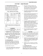
Recommended Troubleshooting Equipment
x
Digital
Voltmeter
x
Digital
Ohmmeter
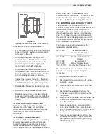
8.4.1 DETERMINING THE CAUSE
Remove the unit cap to expose the over
temperature limit switches.
Check the setpoint of the unit and the setpoint of
the lower over temperature switch. The lower
over temperature switch must be set a minimum
of 20
o
F higher than the setpoint of the unit. Make
adjustments if necessary.
Often in a boiler system, supply water
temperatures can vary and may be higher than
the system design temperature. Check the
actual outlet water temperature of the unit and
ensure that the lower temperature switch is 20
o
F
or more above the actual discharge water
temperature. In a situation like this it may be
necessary to raise the lower limit setting to 40
0
F
above the system design temperature. If after
raising the lower limit switch setting the water
temperature the fault still persists, see Section
8.4.2.
It is sometimes common for a unit to over-temp
when it is being controlled by an external energy
management system that also controls the
system pump(s). The external energy
management system may not be interlocked to
the unit(s) to disable the unit(s) in the event that
the system pump or other system component
should fail. Typically in an over-temperature
situation of this nature the upper, manual reset,
temperature limit switch is tripped.
Reset the unit and, if necessary, the upper over
temperature limit switch. If the unit will not reset
,
proceed to section 8.4.2.
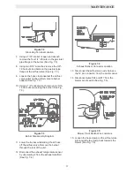
8.4.2 OVER TEMPERATURE LIMIT
SWITCHES
1. Disconnect AC power to the unit.
2. Raise the temperature limit switch setpoint a
minimum of 10
0
F above the actual
discharge water temperature.
3. Referring to system schematic 161413 in
Appendix H, remove wires #18 and #33 from
the lower switch and wires #19 and #33 from
the upper switch.
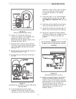
4. Using an ohmmeter, check for continuity
across the C, common, and NC, normally
closed, terminals of both switches.
5. Replace the switches if either or both show
no continuity.
6. If the switches show continuity, disconnect
the 15 pin connector from the control panel.
7. Using an ohmmeter, check wires #18, #19
and #33 back to the 15 pin connector for
continuity.
8. Check for loose connectors on the switch
end of wire's #18, #19 and #33.
Содержание AERCO KC Series
Страница 51: ...TROUBLESHOOTING 41...
Страница 65: ...APPENDIX C ix...
Страница 72: ...APPENDIX F xvi...
Страница 74: ...APPENDIX F xviii...
Страница 76: ...APPENDIX G xx...
Страница 77: ...APPENDIX G xxi...
Страница 78: ...APPENDIX H xxii...
Страница 79: ...APPENDIX H xxiii...
Страница 80: ...APPENDIX H xxiv...