Benchmark 5000-6000 Boiler Installation & Startup Manual
SECTION 2:
INSTALLATION
OMM-0123_E
• GF-207 • 12/17/2019 Technical Support • (800) 526-0288 • Mon-Fri, 8 am - 5 pm EST Page
33
of
95
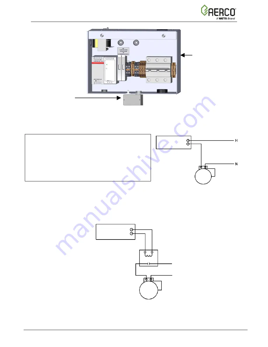
Figure 2-15: Pump Relay Location
Figure 2-16: Schematic
–
System Pump Start using Boiler Pump Relay
If pump/valve load exceeds the above contact ratings, use a separate contact relay, as shown in
Figure 2-17.
Figure 2-17: Schematic
–
System Pump Start using a Separate Contact Relay
The Benchmark pump relay (SPDT) contact is rated for:
10 A Resistive @ 277 VAC/28 VDC
1/3 HP N/O @ 120/240 VAC
1/6 HP N/C @ 120/240 VAC
480 VAC Pilot Duty @ 240-277 VAC Pilot Duty
Heating Pump
Pump Relay Terminals
(Orange)
– N/O
(Yellow) - COM
Contact Relay
(Supplied by Others)
N
H
POWER PUMP(S) FROM
INDEPENDENT FUSED
CIRCUITS
(Orange)
– N/O
(Yellow) - COM
Heating Pump
Pump Relay Terminals
POWER BOX
PUMP RELAY


