background image

Benchmark 5000-6000 Operation & Maintenance Manual


SECTION 3 

– MODES OF OPERATION 


OMM-0118_B


  GF-203 

  5/9/2019        

Technical Support


  (800) 526-0288  

  Mon-Fri, 8 am - 5 pm EST        Page 34  of 148 


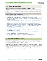
NOTE: 

If  a  voltage,  rather  than  current  signal  is  used  to  control  the  remote  setpoint,  a  DIP  switch 
adjustment  must  be  made  on  the  CPU  Board  located  in  the  C-More  Controller  Assembly. 
Contact your local AERCO representative for details. 

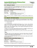
To  enable  the  DIRECT  DRIVE  mode,  the  following  menu  setting  must  be  made  in  the 

Configuration

 menu: 

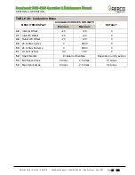
TABLE 3-3: Direct Drive Mode Settings 

MENU OPTION 

SETTING 

Boiler Mode 

Direct Drive 

Remote Signal 

4-20mA/1-5V, 0-20mA/0-5V, or Network 

Refer to Section 2.3 for instructions on changing C-More Controller menu options. 

If the Network setting is selected for RS-485 Modbus operation, a valid Comm Address must be 
entered  in  the 

Setup

  menu.  Refer  to  Modbus  Communication  Manual  GF-114  for  additional 

information. 

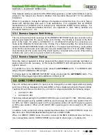
3.4.1  Direct Drive Field Wiring  

The only wiring connections necessary for DIRECT DRIVE mode are connection of the remote 
signal leads from the source to the unit’s I/O Box. For either a 4-20mA/0-5V or a 0-20mA/0-5V 
setting,  the  connections are  made  at  the  ANALOG  IN  terminals  in  the  I/O  Box.  For  a  Network 
setting,  the  connections are  made  at  the  RS-485  COMM terminals  in  the  I/O Box.    The  signal 
must  be  floating,  (ungrounded)  at  the  I/O  Box  and  the  wire  used  must  be  a  two  wire  shielded 
pair  from  18  to  22  AWG.  Polarity  must  be  observed.  The  source  end  of  the  shield  must  be 
conn

ected  at  the  source.  When  driving  multiple  units,  each  unit’s  wiring  must  conform  to  the 

above. 

3.4.2  Direct Drive Startup  

Since  this  mode  of  operation  is  factory  preset  and  the  valve  position  is  being  externally 
controlled, no startup instructions are necessary

.

 In this mode, the REMOTE LED will light when 

the signal is present. 

To operate the unit in MANUAL mode, press the 

AUTO/MAN

 switch.  The REMOTE LED will go 

off and the MANUAL LED will light (password required).  

To  change  back  to  the  DIRECT  DRIVE  mode,  simply  press  the 

AUTO/MAN

  switch.    The 

REMOTE LED will again light and the MANUAL LED will go off. This will happen automatically 
after 1 hour after the password has expired.  


Содержание Aerco Benchmark OMM-0117

Страница 1: ...is subject to change without notice from AERCO International Inc AERCO makes no warranty of any kind with respect to this material including but not limited to implied warranties of merchantability a...

Страница 2: ...27 SECTION 3 MODES OF OPERATION 30 3 1 INDOOR OUTDOOR RESET MODE 30 3 1 1 Reset Ratio 30 3 1 2 Building Reference Temperature 30 3 1 3 Outdoor Air Temperature Sensor Installation 30 3 1 4 Indoor Outdo...

Страница 3: ...62 5 1 INTRODUCTION 62 5 2 ADDITIONAL FAULTS WITHOUT SPECIFIC FAULT MESSAGES 75 SECTION 6 AERTRIM OPERATION 81 6 1 AERTRIM INTRODUCTION 81 6 2 AERTRIM ACTIVATION 81 6 3 OPERATION DETAILS 82 6 4 AERTR...

Страница 4: ...intenance Manual CONTENTS OMM 0118_B GF 203 5 9 2019 Technical Support 800 526 0288 Mon Fri 8 am 5 pm EST Page 4 of 148 APPENDIX H C MORE CONTROLLER VIEWS 141 APPENDIX I RECOMMENDED SPARES 143 APPENDI...

Страница 5: ...ut and output ranges Benchmark 5000 6000 Boiler Intake and Output Ranges MODEL INPUT RANGE BTU HR OUTPUT RANGE BTU HR MINIMUM MAXIMUM MINIMUM MAXIMUM 5000 400 000 117 kW 5 000 000 1465 kW 348 000 102...

Страница 6: ...agement Systems BLDG Bldg Building BST AERCO on board Boiler Sequencing Technology BTU British Thermal Unit A unit of energy approximately equal to the heat required to raise 1 pound 0 45 kg of water...

Страница 7: ...ion and KC1000 Series products IP Internet Protocol ISO International Organization for Standardization Lbs Pounds 1 lb 0 45 kg LED Light Emitting Diode LN Low Nitrogen Oxide MA mA Milliampere 1 thousa...

Страница 8: ...ial full duplex FDX transmission of data based on the RS422 Standard RS485 or EIA 485 A standard for serial half duplex HDX transmission of data based on the RS485 Standard RTN Rtn Return SETPT Setpt...

Страница 9: ...dition It must be given to the user by the installer and kept in a safe place for future reference WARNING Do not use matches candles flames or other sources of ignition to check for gas leaks Fluids...

Страница 10: ...boiler room provide a manually operated remote shutdown switch or circuit breaker marked for easy identification at a location readily accessible in the event of boiler mis operation Design the system...

Страница 11: ...on the floor level where the gas equipment is to be installed In addition the installing plumber or gasfitter shall observe that a battery operated or hard wired carbon monoxide detector with an alarm...

Страница 12: ...or venting system components with the equipment the instructions provided by the manufacturer for installation of the equipment and the venting system shall include 1 Detailed instructions for the in...

Страница 13: ...by factory trained personnel may void the equipment warranty In addition the following WARNINGS and CAUTIONS must be observed at all times WARNING ELECTRICAL VOLTAGES IN THIS SYSTEM INCLUDE 120 208 46...

Страница 14: ...er s front panel shown in Figure 2 1 This panel contains all of the controls indicators and displays necessary to operate adjust and troubleshoot the boiler These operating controls indicators and dis...

Страница 15: ...ws header temperature 3 VFD Display Vacuum Fluorescent Display VFD consists of 2 lines each capable of displaying up to 16 alphanumeric characters The information displayed includes Startup Messages F...

Страница 16: ...enu item is flashing pressing the arrow key will increment the selected setting DOWN Arrow When in one of the main menu categories Figure 2 2 pressing this key will select the displayed menu category...

Страница 17: ...ating each menu and option is accomplished using the menu keys shown in Figure 2 1 Therefore it is imperative that you be thoroughly familiar with the following basic steps before attempting to perfor...

Страница 18: ...Section 6 in the Benchmark 5000 6000 Installation and Startup Guide OMM 0117 GF 202 for instructions Figure 2 2 Menu Structure NOTE The following sections provide brief descriptions of the options con...

Страница 19: ...C 240 F 116 C 2 Outlet Temp 30 F 1 1 C 240 F 116 C Configuration Menu 3 Inlet Temp 30 F 1 1 C 240 F 116 C 4 Air Temp 70 F 56 7 C 245 F 118 C 5 Outdoor Temp 70 F 56 7 C 130 F 54 4 C Configuration Menu...

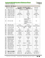
Страница 20: ...is also used to enter date and time and units of temperature measurements A view only software version display is also provided to indicate the current C More Controller software version TABLE 2 3 SE...

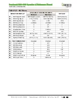
Страница 21: ...anges will be required TABLE 2 4 CONFIGURATION Menu MENU ITEM DISPLAY AVAILABLE CHOICES OR LIMITS DEFAULT Minimum Maximum 1 Internal Setpt 40 F 4 4 C 240 F 115 6 C 130 F 54 4 C 2 Unit Type BMK Blr Std...

Страница 22: ...5 C 22 Network Timeout 5 sec 999 sec 30 sec 23 Shutoff Dly Temp 0 F 0 C 25 F 13 75 C 10 F 5 5 C 24 Demand Offset 0 F 0 C 25 F 13 75 C 10 F 5 5 C 25 Deadband High 0 F 0 C 25 F 13 75 C 5 F 2 75 C 26 Dea...

Страница 23: ...speed of the unit s blower motor based on air temperature and air density at prescribed Air Fuel Valve positions open This is accomplished by providing a DC drive voltage to the motor which then adju...

Страница 24: ...in the item list The Items contained in group 1 BST Monitor Items are always displayed within the menu as these items are critical for proper system operation Therefore the BST Monitor Items Header it...

Страница 25: ...hutdown System Shutdown 26 One Boiler Mode Off On Outlet Temp On Avg Temp Off 27 1 Blr Threshold 10 35 25 28 Setpoint Setback Disable Enable Disable 29 Setback Setpoint BST Setpt Lo Limit BST Setpt HI...

Страница 26: ...Gain 0 00 2 00 0 50 50 BST Deriv Time 0 00 Min 2 00 Min 0 10 Min 51 BST Deadband Hi 0 25 1 52 BST Deadband Lo 0 25 1 53 Deadband En Time 0 120 Sec 30 Sec 54 BST FR Up Rate 1 120 20 55 BST Bldg Ref Tm...

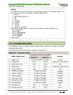
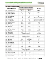
Страница 27: ...alibration menu is used by factory trained service personnel to adjust or reset the parameters listed below A full description of each item appears in Table A 6 of Appendix A TABLE 2 8 Calibration Men...

Страница 28: ...e Pct 60 100 70 23 PWM In Adj 5 0 5 0 0 0 24 Analog In Adj 5 0 5 0 0 0 25 Flow In Adj 5 0 5 0 0 0 26 Supply Gas Pressure In Adj 5 0 5 0 0 0 27 Gas Plate dp In Adj 5 0 5 0 0 0 28 mA Out Adj 1 0 mA 1 0...

Страница 29: ...MENU ITEM DISPLAY AVAILABLE CHOICES OR LIMITS DEFAULT Minimum Maximum 46 Inlet Air Offset 20 20 0 47 Inlet Wtr Offset 20 20 0 48 Outlet Wtr Offset 20 20 0 49 24 hr Max Cycles 0 9999 0 50 24 hr Max Ovr...

Страница 30: ...ader temperature will increase by that number for each degree that the outside air temperature decreases For instance if a reset ratio of 1 6 is used for each degree that outside air temperature decre...

Страница 31: ...Section 2 3 above for detailed instructions on menu changing 7 Press the CHANGE key The display will begin to flash 8 Use the and arrow keys to select the desired Building Reference Temperature 9 Pre...

Страница 32: ...setting for the REMOTE SETPOINT mode is 4 20 mA 1 5 VDC With this setting a 4 to 20 mA 1 to 5 VDC signal sent by an EMS or BAS is used to change the unit s setpoint The 4 mA 1V signal is equal to a 40...

Страница 33: ...source When driving multiple units each unit s wiring must conform to the above 3 3 2 Remote Setpoint Startup Since this mode of operation is factory preset and the setpoint is being externally contr...

Страница 34: ...for DIRECT DRIVE mode are connection of the remote signal leads from the source to the unit s I O Box For either a 4 20mA 0 5V or a 0 20mA 0 5V setting the connections are made at the ANALOG IN termi...

Страница 35: ...to Modbus Communication Manual GF 114 To enable the ACS mode the following menu settings must be made in the Configuration menu TABLE 3 4 ACS Mode Settings MENU OPTION SETTING Boiler Mode Direct Drive...

Страница 36: ...t combination boilers that are Domestic Hot Water Priority DHW PRIORITY boilers along with building heat BLDG HEAT boilers and one hydronic isolation valve in the main header between the BLDG HEAT boi...

Страница 37: ...Mode Settings MENU OPTION SETTING Boiler Mode Combination Remote Signal Network Internal Setpt 40 F to 190 F 4 4 C to 87 8 C Refer to Section 2 3 for instructions on changing C More Controller menu op...

Страница 38: ...Schedule SEC ITEM 6 MOS 12 MOS 24 MOS LABOR TIME 4 2 Pilot Burner Ignitor Rod FRU Kit P N 58084 Inspect Inspect replace if necessary Replace 15 mins 4 3 Main Flame Detector FRU P N 65182 Inspect Inspe...

Страница 39: ...Burner P N 29700 is located on the right front of the Burner Plate It contains an ignition cable the Pilot gas line connected to the bushing and the Pilot Burner Rod P N 66100 which should be inspecte...

Страница 40: ...then the elbow from the Pilot Burner 6 Remove one of the two Pilot Flame Detectors to provide clearance for Pilot Burner removal 7 Using a 1 1 2 open end wrench loosen and remove the Pilot Burner from...

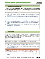
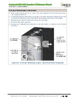
Страница 41: ...h temperature TFE Based thread sealant and reinstall the Main Flame Detector on the Blower Flange 7 Reconnect the Main Flame Detector lead wire 8 Replace the front panel on the unit 4 4 O2 SENSOR The...

Страница 42: ...If corroded the sensor should be replaced Ensure that the hole in the refractory is clean and that the gas sample suction tube is not clogged 6 Reinstall the O2 sensor and crush washer on the back pl...

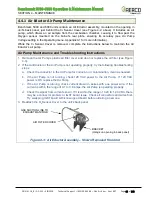
Страница 43: ...Pump s plastic air filter cover and clean or replace the air filter see Figure 4 3 2 If the Air Eductor or the Air Pump is not operating properly try the following troubleshooting steps a Check the co...

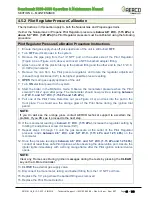
Страница 44: ...s supply shut off valve upstream of the unit is still turned OFF 2 Turn OFF electrical power to the system 3 Remove the 1 4 NPT plug from the Tee on the outlet side of the Pilot Regulator Figure 4 4a...

Страница 45: ...NPT PLUG Install manometer here for Pilot Regulator tests PILOT REGULATOR PILOT SOLENOID VALVES TO AIR FUEL VALVE GAS INLET MANUAL SHUT OFF VALVE HIGH GAS PRESSURE SWITCH BMK 6000 10 5 W C 2 6 kPa BMK...

Страница 46: ...UAL mode Observe the manometer pressure when the Pilot solenoid clicks open after purge The manometer should now provide a reading between 4 6 W C and 5 0 W C 1 15 kPa and 1 25 kPa 9 Pull one of the P...

Страница 47: ...ollowing successful completion of the Combustion Calibration procedures Make sure that the unit is operating in the AUTO mode The MAN light in the upper left of the C More Controller should NOT be lit...

Страница 48: ...e the Pilot sensors and observation ports from the Burner Plate Figure 4 5a below 7 Disconnect the cable from the Pilot Burner by pulling straight out 8 Using a 1 2 open end wrench disconnect the Pilo...

Страница 49: ...avoid tearing the mesh burner fabric or cock the Burner to one side or the other 22 Remove and replace the two 2 Burner Gaskets see Figure 4 6 and clean the gasket surface on the burner front plate 2...

Страница 50: ...r Assembly Mounting Details Left Side View Figure 4 6 Burner Assembly Exploded View GAS TRAIN AIR FUEL VALVE BLOCKED INLET SWITCH BLOWER 5 8 11 BOLTS 4 A F VALVE TO GAS TRAIN BLOWER PROOF SWITCH AIR F...

Страница 51: ...fractory Replacement Instructions 1 Turn off gas and electrical power to the unit In addition turn off any other units sharing the exhaust flue 2 Disconnect the flue from the exhaust manifold of the b...

Страница 52: ...ear refractory Prior to refractory removal mark as necessary using a permanent marker or tape 13 Gently pull on the two opposing metal tabs located on the outer edge of the fiber blanket then alternat...

Страница 53: ...organic binders These organic binders are not hazardous materials however they may emit an odor similar to burning wood 17 Tighten the bolts on the rear plate using an alternating pattern to ensure a...

Страница 54: ...res ceramic fibers can be converted to crystalline silica fibers which have been identified as carcinogenic when inhaled 4 8 2 Front Refractory Replacement As previously mentioned it is much easier to...

Страница 55: ...Maintenance Instructions 1 Disconnect the external condensate trap by loosening and then removing connections on the inlet and outlet sides of the condensate trap see Figure 4 10 2 Loosen the four 4...

Страница 56: ...Remove the front panel from the unit by grasping the handles and pulling outward 3 Refer to Figure 4 11 and locate the air filters attached to the WYE duct connected to the air fuel valve inlet 4 Usin...

Страница 57: ...acitor integrity test consists of two parts as described in the next two sections The first procedure explains how to test for electrical shorting of the LWCO probe capacitor while the second procedur...

Страница 58: ...cedure described in this instruction Serious personal injury or death may occur if this warning is not observed 2 Remove the Shell Harness Cable male connector from the P 5 female connector on the rea...

Страница 59: ...nfirm that the LOW WATER LEVEL message is cleared 4 12 SHUTTING BOILER DOWN FOR EXTENDED PERIOD If the boiler is to be taken out of service for an extended period of time one year or more the followin...

Страница 60: ...piping and connections to the unit 3 Inspect exhaust vent and air inlet duct work if applicable 4 Perform initial startup procedures in Section 4 Initial Startup of the Benchmark 5000 6000 Installatio...

Страница 61: ...nstructions 1 Remove the new actuator cover punch out the holes in the plastic to accommodate the wiring then insert the wires through wire conduit and wire it as follows Wire Terminals 4 5 N N L and...

Страница 62: ...ault Fault Correction Instructions 1 Observe the fault messages displayed in the C More Controller display 2 Refer to the Fault Indication column in Troubleshooting Table 5 1 which follows and locate...

Страница 63: ...chmark 5000 6000 Operation Maintenance Manual SECTION 5 TROUBLESHOOTING GUIDE OMM 0118_B GF 203 5 9 2019 Technical Support 800 526 0288 Mon Fri 8 am 5 pm EST Page 63 of 148 This page intentionally bla...

Страница 64: ...eplace as necessary 4 Remove the Blocked Inlet switch and inspect for signs of blockage clean or replace as necessary 5 Check the continuity of the Blower Proof switch with the combustion blower runni...

Страница 65: ...work leading up to the combustion blower for signs of blockage 5 During the start sequence verify that 24 VAC is present between each side of the switch and ground If 24 VAC is not present refer fault...

Страница 66: ...ween source and unit 2 Check signal at source to ensure it is isolated 3 Check DIP switch on PMC board to ensure it is set correctly for the type of signal being sent Check control signal type set in...

Страница 67: ...urner 5 Blocked condensate drain 6 Main Flame Detector is touching burner mesh 1 Remove and inspect the Flame Detector for signs of wear or cracked ceramic Replace if necessary 2 Check gas pressure re...

Страница 68: ...rrect PID settings 3 Faulty shell temperature sensor 4 Unit in MANUAL mode 5 Unit setpoint is greater than Over Temperature switch setpoint 6 System flow rate changes are occurring faster than units c...

Страница 69: ...wired incorrectly 4 Defective Power Supply Board or fuse 5 Defective IGST Board 1 Start the unit The Air Fuel Valve should rotate to the purge open position If the valve does not rotate at all or doe...

Страница 70: ...EN 1 Interlock jumper not installed or removed 2 Energy Management System does not have unit enabled 3 Device proving switch hooked to interlocks is not closed 1 Check for a jumper properly installed...

Страница 71: ...e 7 VFD failure 1 Remove air filter and clean per Section 4 10 above 2 Inspect all sections of the duct for foreign materials 3 Measure the gas pressure between the SSOV and the Air Fuel Valve It shou...

Страница 72: ...ct wire numbers on the normally open terminals PRG SWTCH CLOSED DURING IGNITION continued 3 Switch wired incorrectly 4 Defective Power Supply Board or fuse 5 Defective IGST Board 3 If the switch is wi...

Страница 73: ...control signal type set in Configuration menu RESIDUAL FLAME 1 Defective Flame Detector 2 SSOV not fully closed 1 Replace Flame Detector 2 Check open close indicator window of Safety Shut Off Valve SS...

Страница 74: ...ve closed either adjust or replace the switch or actuator 4 Ensure that the SSOV Proof of Closure switch is correctly wired STEPPER MOTOR FAILURE 1 Air Fuel Valve out of calibration 2 Air Fuel Valve u...

Страница 75: ...inspect Gas Injector to ensure it is not clogged or damaged 2 Close the 2 Manual Shutoff Valve Attempt to start the unit and listen for a clicking sound that the Ignition Solenoid makes during Ignitio...

Страница 76: ...L VALVE PROPANE TEE with 1 4 PLUG Install manometer here for Pilot Regulator test NATURAL GAS PILOT SOLENOID VALVES PROPANE PILOT REGULATOR NATURAL GAS PILOT GAS VALVE PROPANE PILOT GAS VALVE DOWNSTRE...

Страница 77: ...5 pm EST Page 77 of 148 Figure 5 2 Pilot Burner Flame Detector Locations Figure 5 3 SSOV Actuator With Gas Pressure Adjustment SKP25 BRASS HEX HEAD Remove to access the Gas Pressure Adjustment Screw...

Страница 78: ...Benchmark 5000 6000 Operation Maintenance Manual SECTION 5 TROUBLESHOOTING GUIDE OMM 0118_B GF 203 5 9 2019 Technical Support 800 526 0288 Mon Fri 8 am 5 pm EST Page 78 of 148 Continued on Sheet 2...

Страница 79: ...ntenance Manual SECTION 5 TROUBLESHOOTING GUIDE OMM 0118_B GF 203 5 9 2019 Technical Support 800 526 0288 Mon Fri 8 am 5 pm EST Page 79 of 148 Figure 5 4a Pilot Assembly Troubleshooting Flow Chart She...

Страница 80: ...peration Maintenance Manual SECTION 5 TROUBLESHOOTING GUIDE OMM 0118_B GF 203 5 9 2019 Technical Support 800 526 0288 Mon Fri 8 am 5 pm EST Page 80 of 148 Figure 5 4b Pilot Assembly Troubleshooting Fl...

Страница 81: ...asuring post combustion oxygen percentages inside the combustion chamber This data is fed through the Electronic Control Unit ECU which is connected to the C More Controller inside the boiler If the o...

Страница 82: ...range are at default values but can be changed as needed However you must enable the Adjust O2 Trgts option in the O2 Trim menu before you can change these settings 6 3 OPERATION DETAILS During opera...

Страница 83: ...e rate The control will then store this as the new BV calibration setting until changed manually or by another cycle of the AERtrim function NOTE When the O2 sensor is off during the 10 hour O2 Sensor...

Страница 84: ...me and day for an auto calibration passes the controller will wait for the boiler to cycle off and go into standby mode before executing the sensor calibration function If desired a manual calibration...

Страница 85: ...AER O2 Time Timer to send O2 data periodically to AERCO s onAER or SD card Trim State Displays the current state of a trim function Fire Rate In Displays the input fire rate Fire Rate Out Displays the...

Страница 86: ...r 18 3 8 5 5 30 3 8 5 5 45 3 8 5 5 60 3 8 5 5 80 3 8 5 5 100 3 8 5 0 O2 Lower Limit must be at least 1 lower than O2 Upper 18 2 5 5 5 4 5 30 2 5 5 5 4 5 45 2 5 5 5 4 5 60 2 5 5 5 5 0 80 2 5 5 5 5 0 10...

Страница 87: ...5 5 45 3 8 5 5 60 3 8 5 5 80 3 8 5 5 100 3 8 5 0 O2 Lower Limit must be at least 1 lower than O2 Upper 18 2 5 5 5 4 5 30 2 5 5 5 4 5 45 2 5 5 5 5 0 60 2 5 5 5 5 0 80 2 5 5 5 5 0 100 2 5 5 5 4 5 O2 Up...

Страница 88: ...ERtrim General Warnings WARNING CAUSE POSSIBLE SOLUTIONS O2 PERCENTAGE LOW O2 Levels less than 2 for more than 30 seconds auto reset when valve comes back in range Dirty filter or poor combustion cali...

Страница 89: ...Trim menu TABLE 6 3 AERtrim Operation Interruption Errors ERROR MESSAGE CAUSE POSSIBLE SOLUTIONS BV Hi Err Trim operation exceeds allowable blower voltage limits Check air filter gas regulator combust...

Страница 90: ...enchmark 5000 6000 Operation Maintenance Manual SECTION 6 AERTRIM OPERATION OMM 0118_B GF 203 5 9 2019 Technical Support 800 526 0288 Mon Fri 8 am 5 pm EST Page 90 of 148 This page intentionally blank...

Страница 91: ...Temp Displays the inlet water temperature 4 Air Temp Air Temp is the air temperature at the input to the Air Fuel Valve This reading is one of the parameters used to control the Blower Motor speed 5...

Страница 92: ...his pump draws a sample of gas across the O2 sensor anytime the boiler has proven flame operation If Air Pump voltage is less than 0 20V or greater than 1 20V for more than 10 seconds a AIR PUMP FAILE...

Страница 93: ...12 31 99 5 Unit of Temp Permits selection of temperature displays in degrees Fahrenheit F or degrees Celsius C 6 Comm Address For RS 485 communications RS232 should have its own programmable password...

Страница 94: ...vailable if Mode Remote Setpoint Direct Drive or Combination Used to set the type of external signal which will be used when operating in the Remote Setpoint Direct Drive or Combination Mode 7 Outdoor...

Страница 95: ...led 21 Setpt Limit Band The Setpoint Limit Band can be set from 0 F to 10 F 0 C to 5 5 C 22 Network Timeout Specifies the timeout value in seconds before a Modbus fault is declared up to 999 seconds 2...

Страница 96: ...and the PID LOOP will again attempt Valve Position corrections Setting range is 0 F 0 C to 25 F 13 75 C Default is 5 F 2 75 C for both Deadband High and Deadband Low 27 IGST Version Displays the versi...

Страница 97: ...e rate will be 100 2 Integral Gain This sets the fraction of the output due to setpoint error to add or subtract from the output each minute to move towards the setpoint Gain is adjustable from 0 00 t...

Страница 98: ...up Guide OMM 0117 GF 202 TABLE A 5 COMBUSTION CAL Menu Item Descriptions MENU OPTION DESCRIPTION 1 CAL Voltage 18 Displays the default DC drive voltage provided to the blower at each Air Fuel Valve po...

Страница 99: ...d or Disabled 8 Inlet Tmp Dsply Enabled or Disabled 9 Valv Pos Out Dsp Enabled or Disabled 10 Exhaust Tmp Dsp Enabled or Disabled 11 Exhaust Safety Enabled or Disabled 12 Flue Material Select flue mat...

Страница 100: ...o be set to AUTO or MANUAL 32 Gas Press Reset Allows the Gas Pressure Reset function to be set to AUTO or MANUAL 33 Min Off Time Allows the minimum Off time to be set from 0 to 10 minutes 34 Stop Leve...

Страница 101: ...ge 20 to 20 either F or C 46 Inlet Air Offset Range 20 to 20 either F or C 47 Inlet Wtr Offset Range 20 to 20 either F or C 48 Outlet Wtr Offset Range 20 to 20 either F or C 49 24 hr Max Cycles Maximu...

Страница 102: ...mark 5000 6000 Operation Maintenance Manual APPENDIX A BOILER MENU DESCRIPTIONS OMM 0118_B GF 203 5 9 2019 Technical Support 800 526 0288 Mon Fri 8 am 5 pm EST Page 102 of 148 This page intentionally...

Страница 103: ...nd date that the unit was disabled FLAME PROVEN Displayed after flame has been detected for a period of 2 seconds Initially the flame strength is shown in After 5 seconds has elapsed the time and date...

Страница 104: ...E LOSS DURING RUN The Flame signal was lost during run HEAT DEMAND FAILURE The Heat Demand Relays on the Ignition board failed to activate when commanded HIGH EXHAUST TEMPERATURE The Exhaust Temperatu...

Страница 105: ...TEMPERATURE display Opn indicates sensor is open circuited PRG SWTCH CLOSED DURING IGNITION The Purge Position Limit switch on the Air Fuel Valve closed during ignition PRG SWTCH OPEN DURING PURGE Th...

Страница 106: ...000 6000 Operation Maintenance Manual APPENDIX B STARTUP STATUS AND DISPLAY MESSAGES OMM 0118_B GF 203 5 9 2019 Technical Support 800 526 0288 Mon Fri 8 am 5 pm EST Page 106 of 148 This page intention...

Страница 107: ...90 100 110 120 130 140 150 160 170 180 190 200 210 220 230 240 250 40 34 4 28 9 23 3 17 2 12 2 6 7 1 1 4 4 10 15 5 21 1 26 7 32 2 37 8 43 3 48 9 54 4 60 65 6 71 1 76 7 82 2 87 8 93 3 98 9 104 4 110 1...

Страница 108: ...5000 6000 Operation Maintenance Manual APPENDIX C SENSOR RESISTANCE VOLTAGE CHART OMM 0118_B GF 203 5 9 2019 Technical Support 800 526 0288 Mon Fri 8 am 5 pm EST Page 108 of 148 This page intentional...

Страница 109: ...Technician Verify factory settings Annually Service Technician Check with combustion calibration test equipment See Section 4 2 of the Benchmark 5000 6000 Installation and Startup Guide OMM 0117 GF 20...

Страница 110: ...s pressure interlocks Monthly Operator See Sections 5 2 and 5 3 of the Benchmark 5000 6000 Installation and Startup Guide OMM 0117 GF 202 Air Fuel Valve purge position switch Annual Service Technician...

Страница 111: ...4 105 116 127 138 149 160 171 182 10 23 3 86 98 110 122 134 146 158 170 182 194 15 26 1 89 102 115 128 141 154 167 180 193 206 20 28 9 92 106 120 134 148 162 176 190 204 218 Header Temperature for a B...

Страница 112: ...130 143 156 169 182 195 208 5 20 6 107 121 135 149 163 177 191 205 219 10 23 3 110 125 140 155 170 185 200 215 15 26 1 113 129 145 161 177 193 209 20 28 9 116 133 150 167 201 218 Header Temperature fo...

Страница 113: ...0 153 166 179 192 205 218 5 15 0 117 131 145 159 173 187 201 215 0 17 8 120 135 150 165 180 195 210 5 20 6 123 139 155 171 187 203 219 10 23 3 126 143 160 177 194 211 15 26 1 129 147 165 183 201 219 H...

Страница 114: ...75 23 9 99 102 105 108 111 114 117 120 123 126 70 21 1 102 106 110 114 118 122 126 130 134 138 65 18 3 105 110 115 120 125 130 135 140 145 150 60 15 6 108 114 120 126 132 138 144 150 156 162 55 12 8...

Страница 115: ...69 1 61030 OUTLET TEMPERATURE SENSOR 70 1 58132 THERMOWELL Replacement Kit 71 1 64081 ECU 72 1 65011 TRANSFORMER 115V 24V 100VA 73 1 65109 12V POWER SUPPLY 74 1 123552 OVER TEMP MANUAL RESET SWITCH 7...

Страница 116: ...HARNESS SHELL 63115 HARNESS AIR INLET SENSOR 63125 1 HARNESS GAS TRAIN 7 SEC IGNITION 63134 Vent FAN POWER WIRE Dual Fuel Only 63135 VFD BLOWER POWER WIRE 10 AWG 63162 HARNESS DOUBLE OPTICAL SENSOR Be...

Страница 117: ...9 2019 Technical Support 800 526 0288 Mon Fri 8 am 5 pm EST Page 117 of 148 AERCO International Inc Blauvelt NY 10913 Benchmark 5000 6000 Part List 10 12 2017 Whole Boiler P N 28500 BMK 6000 28657 BMK...

Страница 118: ...5 9 2019 Technical Support 800 526 0288 Mon Fri 8 am 5 pm EST Page 118 of 148 NOTE Complete Air Fuel Valve Blower and Burner part part list shown below AERCO International Inc Blauvelt NY 10913 Bench...

Страница 119: ...PART LIST DRAWINGS OMM 0118_B GF 203 5 9 2019 Technical Support 800 526 0288 Mon Fri 8 am 5 pm EST Page 119 of 148 AERCO International Inc Blauvelt NY 10913 Benchmark 5000 6000 Part List 10 12 2017 W...

Страница 120: ...ical Support 800 526 0288 Mon Fri 8 am 5 pm EST Page 120 of 148 AERCO International Inc Blauvelt NY 10913 Benchmark 5000 6000 Part List 10 12 2017 Whole Boiler P N 28500 BMK 6000 28657 BMK 5000 Sheet...

Страница 121: ...ESSES not shown QTY PART DESCRIPTION 1 63004 HARNESS 460V TRANSFORMER 1 63090 HARNESS ASSY TEMP LIM CONT PWR 1 63104 I O INTERLOCK HARNESS 1 63105 I O SENSOR COMM HARNESS 1 63111 HARNESS CONTROL 1 631...

Страница 122: ...FLANGE SSOV 2 NPT 4 1 99015 DAMPING ORIFICE SSOV 21 1 60020 GAS PRESSURE SWITCH 2 20 W C 7 4 12951 2 BUSHING CONTROL BOX 25 1 27086 2 ACTUATOR SSOV w POC SWITCH 10 4 9 22 PIPE PLUG 1 4 NPT STEEL 26 1...

Страница 123: ...Benchmark 5000 DF 6000 DF Gas Train P N 22187 Item Qty Part Description 1 1 22185 DUAL FUEL GAS TRAIN NATURAL GAS 2 1 22186 DUAL FUEL GAS TRAIN PROPANE 3 1 970087 26 FLEXIBLE GAS TUBE 26 AERCO Interna...

Страница 124: ...PT 4 1 99015 DAMPING ORIFICE SSOV 24 1 60020 SWITCH GAS PRESSURE 2 20 W C 7 4 12951 2 BUSHING CONTROL BOX 29 1 27086 2 ACTUATOR SSOV w POC SWITCH 10 3 9 22 PIPE PLUG 1 4 NPT STEEL 30 1 99017 SNUBBER P...

Страница 125: ...V DOUBLE BODY 1 1 2 NPT 4 4 12951 2 BUSHING CONTROL BOX 22 1 27086 2 ACTUATOR SSOV w POC SWITCH 6 4 9 22 PIPE PLUG 1 4 NPT STEEL 25 1 99017 SNUBBER PRESSURE 1 4 8 2 58089 SOLENOID VALVE 1 4 NPT 29 1 9...

Страница 126: ...Table BLOWER 15 1 61002 5 BMK 6000 BLOCKED INLET SWITCH 8 0 W C 5 2 59192 OBSERVATION PORT 61002 23 BMK 5000 BLOCKED INLET SWITCH 3 9 W C 6 1 59140 SIGHT GLASS 1 16 1 65150 FLAME ROD ASSY 7 1 24352 BM...

Страница 127: ...Operation Maintenance Manual APPENDIX G WIRING DIAGRAMS OMM 0118_B GF 203 5 9 2019 Technical Support 800 526 0288 Mon Fri 8 am 5 pm EST Page 127 of 148 Appendix G WIRING DIAGRAMS Wiring Diagram 68043...

Страница 128: ...ark 5000 6000 Operation Maintenance Manual APPENDIX G WIRING DIAGRAMS OMM 0118_B GF 203 5 9 2019 Technical Support 800 526 0288 Mon Fri 8 am 5 pm EST Page 128 of 148 Wiring Diagram 68043 rev D Sheet 2...

Страница 129: ...ark 5000 6000 Operation Maintenance Manual APPENDIX G WIRING DIAGRAMS OMM 0118_B GF 203 5 9 2019 Technical Support 800 526 0288 Mon Fri 8 am 5 pm EST Page 129 of 148 Wiring Diagram 68048 rev D Sheet 1...

Страница 130: ...ark 5000 6000 Operation Maintenance Manual APPENDIX G WIRING DIAGRAMS OMM 0118_B GF 203 5 9 2019 Technical Support 800 526 0288 Mon Fri 8 am 5 pm EST Page 130 of 148 Wiring Diagram 68048 rev D Sheet 2...

Страница 131: ...ark 5000 6000 Operation Maintenance Manual APPENDIX G WIRING DIAGRAMS OMM 0118_B GF 203 5 9 2019 Technical Support 800 526 0288 Mon Fri 8 am 5 pm EST Page 131 of 148 Wiring Diagram 68052 rev C Sheet 1...

Страница 132: ...ark 5000 6000 Operation Maintenance Manual APPENDIX G WIRING DIAGRAMS OMM 0118_B GF 203 5 9 2019 Technical Support 800 526 0288 Mon Fri 8 am 5 pm EST Page 132 of 148 Wiring Diagram 68052 rev C Sheet 2...

Страница 133: ...ark 5000 6000 Operation Maintenance Manual APPENDIX G WIRING DIAGRAMS OMM 0118_B GF 203 5 9 2019 Technical Support 800 526 0288 Mon Fri 8 am 5 pm EST Page 133 of 148 Wiring Diagram 68053 rev C Sheet 1...

Страница 134: ...ark 5000 6000 Operation Maintenance Manual APPENDIX G WIRING DIAGRAMS OMM 0118_B GF 203 5 9 2019 Technical Support 800 526 0288 Mon Fri 8 am 5 pm EST Page 134 of 148 Wiring Diagram 68053 rev C Sheet 2...

Страница 135: ...ark 5000 6000 Operation Maintenance Manual APPENDIX G WIRING DIAGRAMS OMM 0118_B GF 203 5 9 2019 Technical Support 800 526 0288 Mon Fri 8 am 5 pm EST Page 135 of 148 Wiring Diagram 68076 rev C Sheet 1...

Страница 136: ...ark 5000 6000 Operation Maintenance Manual APPENDIX G WIRING DIAGRAMS OMM 0118_B GF 203 5 9 2019 Technical Support 800 526 0288 Mon Fri 8 am 5 pm EST Page 136 of 148 Wiring Diagram 68076 rev C Sheet 2...

Страница 137: ...ark 5000 6000 Operation Maintenance Manual APPENDIX G WIRING DIAGRAMS OMM 0118_B GF 203 5 9 2019 Technical Support 800 526 0288 Mon Fri 8 am 5 pm EST Page 137 of 148 Wiring Diagram 68077 rev B Sheet 1...

Страница 138: ...ark 5000 6000 Operation Maintenance Manual APPENDIX G WIRING DIAGRAMS OMM 0118_B GF 203 5 9 2019 Technical Support 800 526 0288 Mon Fri 8 am 5 pm EST Page 138 of 148 Wiring Diagram 68077 rev B Sheet 2...

Страница 139: ...DIX G WIRING DIAGRAMS OMM 0118_B GF 203 5 9 2019 Technical Support 800 526 0288 Mon Fri 8 am 5 pm EST Page 139 of 148 BMK 5000 6000 STANDARD FUEL MODELWIRING DIAGRAMS Standard BMK 5000 6000 Drawing Nu...

Страница 140: ...0 6000 Operation Maintenance Manual APPENDIX G WIRING DIAGRAMS OMM 0118_B GF 203 5 9 2019 Technical Support 800 526 0288 Mon Fri 8 am 5 pm EST Page 140 of 148 Drawing Number 63035 2 rev B Duel Fuel Se...

Страница 141: ...C More Controller Exploded View ENCLOSURE P N 124951 POWER SUPPLY BOARD P N 124362 IGNITION STEPPER BOARD P N 124361 FISH PAPER INSULATOR P N 124960 V F D DISPLAY MODULE P N 124527 FRONT FACE PLATE B...

Страница 142: ...Mon Fri 8 am 5 pm EST Page 142 of 148 Figure H 2 Benchmark C More Controller Rear View SENSOR HARNESS CONNECTOR 7 PIN A F VALVE HARNESS CONNECTOR 16 PIN EXT SENSOR COMM HARNESS CONNECTOR 24 PIN TO INP...

Страница 143: ...SSOV with P O C Switch Kit 27086 2 Actuator Replacement Kit SSOV with Regulator POC Switch Damping Orifice 64106 Pilot Regulator w 2 6 Spring 24384 Pilot Solenoid Valve 1 4 NPT Replacement Kit 58089...

Страница 144: ...mark 5000 6000 Operation Maintenance Manual APPENDIX I RECOMMENDED SPARE PARTS OMM 0118_B GF 203 5 9 2019 Technical Support 800 526 0288 Mon Fri 8 am 5 pm EST Page 144 of 148 This page intentionally b...

Страница 145: ...n equipment etc Accessible for periodical inspection and maintenance 2 The blower should be supported under each corner of its base to allow it to breath Supports 2 x 4 s timbers or railroad ties shou...

Страница 146: ...esistance b DO NOT lubricate the motor bearings during storage Motor bearings are packed with grease at the factory c If the storage location is damp or humid the motor windings must be protected from...

Страница 147: ...Benchmark 5000 6000 Operation Maintenance Manual OMM 0118_B GF 203 5 9 2019 Technical Support 800 526 0288 Mon Fri 8 am 5 pm EST Page 147 of 148 NOTES...

Страница 148: ...Changed by 2 15 2018 Rev A Initial release 5 9 2019 Rev B DIR 18 45 Changed part number of Gas Pressure Switch 60032 to 60032 1 DIR 18 55 Changed Air Inlet Temp Sensor part number from 61024 to 123449...

Отзывы: