17
Need help or have any questions? Call us at 1-714-963-0329 or send us an Email at [email protected]
❑
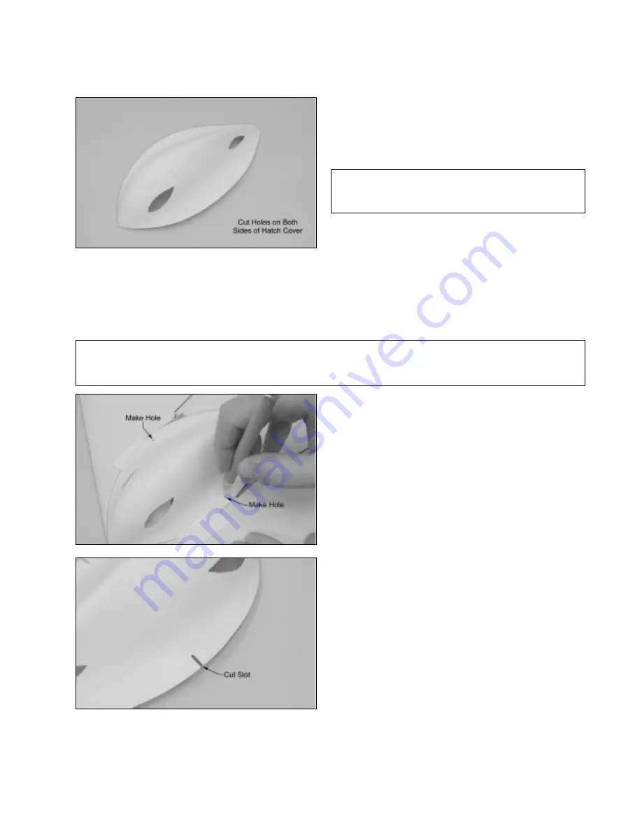
With the hatch cover firmly in place and aligned, use the
tip of your modeling knife to make a pilot hole through each
side of the hatch cover and into the plastic mounting board.
Position each pilot hole over the center of the mounting board.
❑
Set the hatch cover into place and position it. When aligned properly, the hatch cover should be centered over the
centerline of the wing and the base of the hatch cover should fit flush against the top of the wing. In addition, the front of
the hatch cover should conform to the leading edge of the wing and the sides of the hatch cover should not interfere with
the servo arms.
❑
When satisfied with the alignment, hold the hatch cover in place using a couple of pieces of masking tape.
✦
✦
✦
✦
✦
IMPORTANT
✦
✦
✦
✦
✦
If the hatch cover does not fit flush against the top of the wing, it may be because the wiring under the
hatch cover is preventing it. If so, rearrange the wiring to fit. Also, don't forget that you need to cut out the small molded
triangle shape in the back of the hatch cover to allow room for the motor wires to pass through.
❑
Remove the hatch cover and use a modeling knife to
cut a narrow slot from each pilot hole out to the edge of the
hatch cover.
☞
Make the slot wide enough that it will slide over the
threaded portion of the M2 x 10mm flange-head wood screws.
❑
Using a modeling knife, carefully cut an air-intake hole
and an air-exit hole in each side of the hatch cover, as shown.
✦
✦
✦
✦
✦
IMPORTANT
✦
✦
✦
✦
✦
You must cut air-intake and air-exit holes
in the hatch cover to properly cool the flight battery and
ESC. Do not omit this procedure.
❑
Carefully thread the two M2 x 10mm flange-head wood screws into the pilot holes you made in the plastic mounting
board. Thread them in far enough so that the hatch cover will slide just underneath the screw heads.


