Watlow EZ-ZONE
®
ST
•
6
•
Chapter 1 Overview
Ó
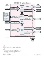
WARNING: When the controller is powered up, the outputs
may turn on .
Note:
A current error can be sent to the RUI (Remote User
Interface) soft error display by enabling Current
Reading
[`CU;r]
in the Setup Page.
Note:
Number of inputs and outputs and various combinations of the same will vary
depending upon part number; see ordering matrix for more detail.
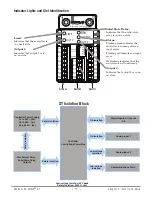
High
Current
Power
Digital Input 5 & 6
(optional)
DC voltage, Dry Contact
Limit Controller
Board
(optional)
Input
Functions
Output
Functions
- None
- Limit reset
- Profile start/stop
- Profile start
- Profile hold/resume
- Profile disable
- TRU-TUNE+
®
disable
- Switch Control Loop Off
- Manual mode
- Tune
- Idle set point
- Force alarm
- Loop & alarms off
- Silence alarm
- Alarm clear, request
- Restore user settings
Analog Input 1
none, Thermocouple, RTD (100Ω,
1kΩ), Process (V, mV, mA)
PID
Controller
(Optional -
Ramp/Soak max 4
files, 40 steps)
Input Sensor
off, heat, cool
alarm, event
Limit
off, heat, cool,
alarm, event, limit
Standard Bus
Zone Address
1 - 16
Supervisory &
Power Board
Modbus
Address 1 - 247
EIA-485 Communication
Standard Bus
(optional Modbus RTU)
*RUI, EZ-ZONE
Controllers, PLC, PC
or HMI
Input Sensor
If Limit, this output must
be Limit
Output 2
5A Mechanical Relay (form A), or
0.5A Solid State Relay (form A)
Output 1
Solid State Relay (form A)
off, heat, cool
Analog Input 2
none, Thermocouple, RTD (100Ω,
1kΩ), Process (V, mV, mA)
Output 3
5A Mechanical Relay (form C)
Output 4
5A Mechanical Relay (form A)
Digital Output 5 & 6
(optional) none, switched dc
off, heat, cool,
event, limit, alarm
Contactor
(optional)
Current Sensor
(optional)
* EZ-ZONE Remote User Interface (RUI)
EZ-ZONE
®
ST System Diagram


