background image

Appendix

33

WATLOW Series 733/734 Service Manual

Warranty

The Watlow Series 733/734 is warranted to be free
of defects in material and workmanship for 36
months after delivery to the first purchaser for use,
providing that the units have not been misapplied.
This excludes mechanical relays which are war-
ranted for 100,000 cycles.

Since Watlow has no control over their use, and
sometimes misuse, we cannot guarantee against
failure.  Watlow's obligations hereunder, at
Watlow's option, are limited to replacement, repair
or refund of purchase price, and parts which upon
examination prove to be defective within the
warranty period specified.  This warranty does not
apply to damage resulting from transportation,
alteration, misuse, or abuse.

Watlow Controls

Watlow Controls is a division of Watlow Electric
Mfg. Co., St. Louis, MO, a manufacturer of indus-
trial electric heating products, since 1922.  Watlow
begins with a full set of specifications and com-
pletes an industrial product that is manufactured
totally in-house, in the U.S.A.  Watlow products
include electric heaters, sensors, controls and
switching devices.  The Winona operation has been
designing solid state electronic control devices
since 1962, and has earned the reputation as an
excellent supplier to original equipment manufactur-
ers.  These OEMs depend upon Watlow Controls to
provide compatibly engineered controls which they
can incorporate into their products with confidence.
Watlow Controls resides in a 100,000 square foot
marketing, engineering and manufacturing facility in
Winona, Minnesota.

Returns

1.

Call Watlow Customer Service, 507/454-5300,
for a Return Material Authorization (RMA)
number before returning any item for repair.
We need this information:
• Ship to address

• Bill to address

• Contact name

• Phone number

• Ship via

• Your P.O. number

• Symptoms and/or special instructions
• Name and phone number of person returning

the material.

2.

Prior approval and an RMA number, from the
Customer Service Department, is needed when
returning any unused product for credit.    Make
sure  the RMA number is on the outside of the
carton, and on all paperwork returned.  Ship on
a Freight Prepaid basis.

3.

After we receive your return, we will examine it
and determine the cause for your action.

4.

In cases of manufacturing defect, we will enter
a repair order, replacement order, or issue
credit for material.  A 20 percent restocking
charge is applied for all returned stock controls
and accessories.

5.

If the unit is unrepairable, it will be returned to
you with a letter of explanation.  Repair costs
will not exceed 50 percent of the original cost.

Shipping Claims

When you receive your Watlow control, examine
the package for any signs of external damage it
may have sustained enroute.  If there is apparent
damage either outside the box or to its contents,
make a claim with the shipper immediately.  Save
the original shipping carton and packing material.

Warranty/Returns

Содержание 733 Series

Страница 1: ...t change W733 XSMN Rev D00 10 00 Made in the U S A Time Temperature Control Total Customer Satisfaction 3 Year Warranty Series 733 734 Watlow Controls 1241 Bundy Blvd P O BOX 5580 Winona MN 55987 5580...

Страница 2: ...all and Wire the Series 733 734 3 Dimensions 3 Panel Cutout 4 How to Wire the Series 733 734 5 Power Wiring 5 Input Wiring 8 Output 1 Wiring 9 Output 2 Wiring 10 Event Input Wiring 10 Event Output Wir...

Страница 3: ...5 2 4 6 7 9 11 EVENT LOAD 1 READY MENUS 10 625 270 mm 3 25 83 mm SERIES 734 1 10 7 4 2 11 8 5 3 12 9 6 EVENT READY LOAD 1 MENUS TL W WA 10 625 270 mm 3 25 83 mm 9 78 248 mm 3 13 80 mm 0 27 Dia 7 mm 2...

Страница 4: ...and compare your model number to those shown here and also the model number breakdown on the inside back cover of this manual When you apply power without sensor inputs on the terminal strip the Serie...

Страница 5: ...a power source and to electrical sensors or peripheral devices 1 2 3 4 5 6 7 8 9 10 11 12 1 2 3 4 5 6 7 8 9 1 0 1 1 1 2 Fuse L2 L1 Power Wiring Input Wiring Use this wiring connector as a reference f...

Страница 6: ...l zone thermo couple units require at least one un grounded thermocouple 1 2 3 4 5 6 Thermocouple Input 73XX 1XXX XXXX Dual Zone Only 73XX 4XXX XXXX 73XX 6XXX XXXX 73XX 4XXX XXXX Zone 1 Zone 2 3 Wire...

Страница 7: ...iring Figure 11 0 5VDC or 0 10VDC Process Input Wiring Figure 12 0 20mA or 4 20mA Process Input Wiring 4 5 6 DC I 4 5 6 Zone 2 Zone 2 0 5VDC or 0 10VDC Process Input Model 73XX 6XXX XXXX Dual Zone Onl...

Страница 8: ...s Form A 1 Amp Off state impedance 20K max Off state impedance 20K min 73XX XBXX XXXX 73XX XDXX XXXX Solid State Relay without Solid State Relay without Contact Suppression Contact Suppression Form A...

Страница 9: ...ontact Suppression Contact Suppression Form A 0 4 Amps Form A 1 Amp Off state impedance 20K max Off state impedance 20K min 73XX XXBX XXXX 73XX XXDX XXXX Solid State Relay without Contact Suppression...

Страница 10: ...3 4 5 6 7 8 9 Event Input 2 Common Event Input 1 1 2 3 4 5 6 7 8 9 1 0 1 1 1 2 External Load COM L1 L2 Fuse Event Input Wiring 2 Event Inputs Non isolated 73XX XXX1 XXXX Event Output Wiring 4 Event Ou...

Страница 11: ...36XX 1200 UL recognized safety limit control Reset L2 High Limit Mechanical Contactor A001 0249 0001 6 9 3 2 73XX 1CA0 AXXX NC C L1 NO Over Temp Light 1 L2 2 2 3 7 8 1 2 1 2 3 14 21 15 16 17 18 2 1CR...

Страница 12: ...ne 1 alarm low HyS1 A1LO Zone 1 calibration offset Zone 2 input type CAL1 InP2 Zone 2 range low Zone 2 range high rL2 rH2 Zone 2 hysteresis Zone 2 alarm low HyS2 A2LO Zone 2 alarm high Zone 2 alarm ty...

Страница 13: ...rtd for Zone 1 or InP2 rtd for Zone 2 This parameter only appears if you have a unit with RTD input JIS 0 003916 C DIN 0 003850 C Range din or JIS Default din Temperature Compensation WatCurve Automa...

Страница 14: ...high to rL1 Default High limit of sensor type Hysteresis 1 Selects the switching hysteresis for Zone 1 when Pb1 0 ON OFF See Page 17 for the Pb1 parameter Range 1 to 99 F 1 to 55 C Default 3 F Alarm...

Страница 15: ...ol Range Sensor range high to rL2 Default High limit of sensor type Hysteresis 2 Selects the switching hysteresis for Zone 2 when Pb2 0 ON OFF See Page 17 for the Pb2 parameter This parameter only app...

Страница 16: ...0 to 555 C AL1 no If AL1 Pr A1LO to rH1 rH1 CAL1 99 to 99 F 55 to 55 C 99 to 99Units 0 InP2 J K appears as H E or J or rtd or 0 5 Dependent on model rtd or 0 5 420 010 020 number information rL2 Senso...

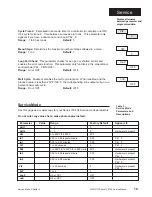
Страница 17: ...e the UP DOWN keys to select data After 1 minute without key activa tions the Series 733 734 reverts to the Operation mode 0 0 Parameter may not appear depending on control configuration SERIES 733 TL...

Страница 18: ...es the set point to minimize overshoot and or undershoot The rate is determined by how fast the error is changing This parameter only appears if Pb1 0 Range 0 00 to 9 99 minutes Default 0 00 Cycle Tim...

Страница 19: ...5 StP LooP nnS Cycle Time 2 Expressed in seconds time for a controller to complete one ON OFF cycle for Zone 2 Time between successive turn ons This parameter only appears if you have a dual zone con...

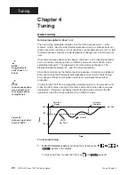
Страница 20: ...of control at 90 of the established set point The displayed set point remains unchanged The display alternates between At _ and the current parameter Once the control learns the thermal system respon...

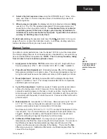
Страница 21: ...e stabilizes to a constant value The process temperature may not be right on set point because the initial reset value is 0 00 repeats per minute 3 Reset Adjustment Gradually increase rE until the dis...

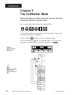
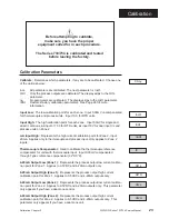
Страница 22: ...order for the control to go through its auto calibration Press the TIME key to advance through the Calabration Menu Use the UP DOWN keys to change data After 1 minute with no key activactions the Seri...

Страница 23: ...t c versions or input 317 33 for RTD units or input 10V for dual input t c and process units on Zone 2 mA Input High Represents the high current calibration point for Zone 2 input 20mA Applies only to...

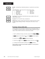
Страница 24: ...ess the Time key 5 The Series 733 734 will beep and advance to the LgOt parameter This procedure is only to be used to restore calibration It is not meant to default any other values Restore Restores...

Страница 25: ...llivolt source to Terminal 5 Positive and Terminal 6 Negative on the Series 733 734 terminal strip Use regular 20 24 gauge wire 3 Apply power to the unit and allow it to warm up for 15 minutes After w...

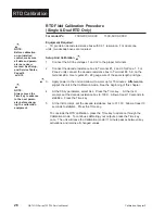
Страница 26: ...nal 1 2 and 3 for Zone 1 For Zone 2 units connect the decade resistance box to Terminal 4 5 6 on the terminal strip Use regular 20 24 gauge wire of the same length and type 3 Apply power to the unit a...

Страница 27: ...20 24 gauge wire 3 Apply power to the unit and allow it to warm up for 15 minutes After warm up put the unit in the CAL menu See the beginning of this chapter 4 At the CALy parameter select ALL At th...

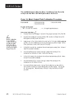
Страница 28: ...or 2 Negative and 3 Positive for Zone 1 3 Apply power to the unit and allow it to warm up for 15 minutes After warm up put the unit in the Calibration mode See the beginning of this chapter At the CAL...

Страница 29: ...t connector 2 Negative and 3 Positive for Zone 1 3 Apply power to the unit and allow it to warm up for 15 minutes After warm up put the unit in the Calibration mode See the beginning of this chapter A...

Страница 30: ...vershoot and undershoot Also rate Deviation alarm An alarm referenced at a fixed number of degrees plus or minus from set point Default parameters The parameters permanently stored in memory to provid...

Страница 31: ...e Detector Resistive sensing device displaying resistance versus tempera ture characteristics Displays positive temperature coefficient Set point Intended value of the process variable Shelf Timing Co...

Страница 32: ...9 Alarm Wiring 10 Model Number 35 Mounting 3 O Output 1 Wiring 8 Output 2 Wiring 9 Index P Panel Cutout 3 Power Wiring 5 Process Calibration 28 29 Input Wiring 4 7 Output 1 8 Output 2 9 Proportional B...

Страница 33: ...ngineered controls which they can incorporate into their products with confidence Watlow Controls resides in a 100 000 square foot marketing engineering and manufacturing facility in Winona Minnesota...

Страница 34: ...t Zone 2 Solid state Relay Form A 0 4A 120 208 240V VAC 30VA pilot duty 120 208 240V VAC opto isolated zero cross switching Off state imped ance is 20K minimum with contact suppression 31M without con...

Страница 35: ...e relay without RC suppression form A 0 4A Output 2 Type A None B Solid state relay with RC suppression form A 0 4A C Switched DC open collector non isolated D Mechanical relay form A 1A with suppress...

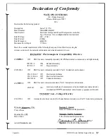
Страница 36: ...y standard Part I Residential commercial and light industry IEC 801 3 1984 Radiatedimmunity IEC 801 5 1991 Surgeimmunity 1995 EMC Generic immunity standard Part 2 Industrial environment EN 6 1000 4 2...

Страница 37: ...Appendix 37 WATLOW Series 733 734 Service Manual Notes...

Страница 38: ...Appendix 38 WATLOW Series 733 734 Service Manual Notes...

Страница 39: ...Appendix 39 WATLOW Series 733 734 Service Manual...

Страница 40: ...Appendix 40 WATLOW Series 733 734 Service Manual Watlow Series 733 734 Service Manual Watlow Controls 1241 Bundy Blvd P O Box 5580 Winona MN 55987 5580 507 454 5300 Fax 507 452 4507...

Отзывы: