background image

1

46°

INSTALLATION REQUIREMENTS

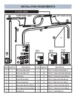
KIT INCLUDES

PART

QUANTITY

DESCRIPTION

PART

QUANTITY

DESCRIPTION

A

1

Pivot Assembly, Right 

I

8

#10 x 1” Square Flat Head (Bag 1)

B

1

Pivot Assembly, Left 

J

8/8

#10 X 1

½

” Square Flat Head (Bag 1&2)

C

2

Gas Spring 

K

12

#10 X 1

½

” Square Pan Head (Bag 2)

D

1

Crosslink Assembly 

L

8

#10 X 2” Square Flat Head (Bag 3)

E

2

Side Arm Assembly 

M

12

#10 X 2” Square Pan Head (Bag 3)

F

2

Side Hinge with Screw (Bag 1)

N

8

#10 X 2

½

” Square Flat Head (Bag 4)

G

2

Back Hinge with Screw (Bag 1)

O

12

#10 X 2

½

” Square Pan Head (Bag 4)

H

1

Template 46° 

P

4

¼

-20 x

¾

” Hex Bolt (Bag 1)

A

B

C

D

E

F

G

H

BAG #1
(72574)

BAG #2 
(72575)

BAG #3 
(72576)

BAG #4 
(75104)

P

I

J

J

K

L

M

N

O

2x

2x

RIGHT PIVOT ASSY.

LEFT PIVOT ASSY.

Содержание COVER CRADLE

Страница 1: ...TALL PREPARATION LOCATE PLATES COVER CRADLE INSTALLATION 4 ATTACH BACK HINGES ATTACH SIDE HINGES ASSEMBLE CROSSLINK COVER CRADLE INSTALLATION 5 ATTACH CROSSLINK ASSY COVER CRADLE INSTALLATION 7 ATTACH...

Страница 2: ...10 X 1 Square Pan Head Bag 2 D 1 Crosslink Assembly L 8 10 X 2 Square Flat Head Bag 3 E 2 Side Arm Assembly M 12 10 X 2 Square Pan Head Bag 3 F 2 Side Hinge with Screw Bag 1 N 8 10 X 2 Square Flat He...

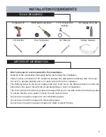
Страница 3: ...ing side of the spa for cover to operate properly and 4 on each side for Side Arm clearance The Warning Label on the cover is always the front of the cover the lifter will attach on either the back si...

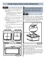
Страница 4: ...ver Position the cover evenly on all spa sides See Figure 1 3 Figure 1 4 Warning Label Hidden Aluminum Plate Back Side to Side Wa rni ng La be l The cover warning label must be facing the front of the...

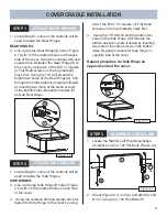
Страница 5: ...es SIDE HINGES 2 Line up the top Side Hinge F holes Figure 2 2 with 2 of the marked holes on one side of the cover 3 Using the cordless drill and square drive bit fasten the Side Hinge to the cover by...

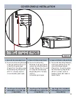
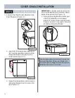
Страница 6: ...ure 5 2 IMPORTANT Carefully examine cover to be sure it is still aligned evenly with the outside edges of the spa bar top Figure 1 3 4 Using the Mounting Bracket bottom part of the Pivot Assembly as a...

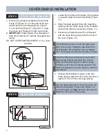
Страница 7: ...important information on screw size compatibility NOTE See Page 2 for important information on screw size compatibility NOTE 5 Secure the Mounting Brackets to the spa cabinet using 12 of the Pan Head...

Страница 8: ...e Plastic Bottom Pivot Bracket with the holes facing away from the back of the cover Figure 7 2 4 Holding Pivot Bracket in place mark all 4 holes and pre drill with 1 8 3mm drill bit at a depth of 1 2...

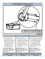
Страница 9: ...or important information on screw size compatibility NOTE See Page 2 for important information on screw size compatibility NOTE 5 Secure the Side Arm Assembly E to the spa cabinet using 4 of the Flat...

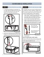
Страница 10: ...the following a Remove both Gas Springs by reversing the order in Step 7 Remove Gas Springs from each ball stud by placing a flat blade screwdriver behind the retaining cup hold up the clip with the s...

Страница 11: ...10 COVER CRADLE INSTALLATION Always ease the cover to the Open and Close Position to avoid Slamming thereby prolonging the service life of your cover NOTE BLANK...

Страница 12: ...62733 C 04 19...
Отзывы: