background image


Ecostream

 Manual 

                                                      Page 47 - Revision: 11-13-2020 

Pre-installation and sanitization procedures as prescribed in this manual must be performed 

before installing the 

ECOSTREAM Water Treatment System


Always install indoors and place the 

Waterlogic ECOSTREAM


Water Treatment System


on a 

firm, flat and stable surface.     


1.


Attach the water supply line to the 1/4” feed water inlet bulkhead fitting on the back of 

the 

ECOSTREAM


Water Treatment System.


Waterlogic

 requires the use of a water 

pressure regulator.  Water feed pressure must be between 40-60 psi.   Turn on the water 

supply and check for leaks. 


2.


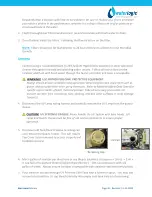
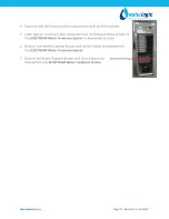
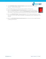
Check to ensure that the Red Heater and Compressor Power Switch is the 

O=OFF 

p

osition.  


NOTE:

  Switches have internal LED that illuminates when placed in 

I=ON

 position. 


3.


Connect the power cord to the back of the 

Waterlogic ECOSTREAM


Water 

Treatment System


and to a 120 Volt supply. 


4.


Fill the Cold Tank.  Hold a container under the dispensing faucet, press and hold the main 

dispensing button until a continuous flow of water is obtained.  Once a continuous flow is 

obtained, release the dispensing button.  Cold tank is now full.   


5.


Fill the Hot Tank.  Hold a container under the dispensing faucet.  Press the Hot Select 

Button followed by the main dispensing button until a continuous flow of water is 
obtained.  Once a continuous flow is obtained, release the main dispensing button.  Hot 

tank is now full.  


       CAUTION!  

NEVER TURN ON HEATER BEFORE FILLING HOT TANK. 

Red Heater and Compressor Power Switch


must be in the O=OFF position while 

the Hot Tank is empty.  Damage could occur within one minute and the overload 

(high limit) will require manual reset if heater is turned on with an empty Hot 

Tank.  


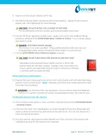
6.


Verify that the UV Lamp operates as expected. 


WARNING!  

ULTRAVIOLET RADIATION.  

Protect your skin and eyes against ultraviolet 

rays.  Never look directly at an operating UV light. Always disconnect before removal.


7.


Move the 

Waterlogic ECOSTREAM


Water Treatment System


into its final operating 

position.  Be sure that a minimum of 2” clearance is maintained around both sides and 

the back of the 

ECOSTREAM


Water Treatment System

.   


8.


This is important to allow proper airflow and heat exchange of refrigeration system.  


Содержание Ecostream

Страница 1: ...s Pro Drive Grapevine TX 76051 800 288 1891 www waterlogicdealers com Tech Portal Website canteen portal waterlogic com Waterlogic International LTD Global Headquarters Grenfell Road Maidenhead Berksh...

Страница 2: ...oy trained service personnel who are experienced in the installation function and repair of this equipment This publication is written for use by these qualified individuals Waterlogic encourages user...

Страница 3: ...15 Resetting the Hot Tank Overload High Limit Safety 16 Hot Tank Descaling 18 Replacement Components Consumables 20 Countertop Drawings and Parts List 21 Tower Drawings and Parts List 28 Counter Top...

Страница 4: ...perated installed or maintained The installation maintenance sanitizing and any repair must be performed by qualified persons trained by Waterlogic International or their approved distributors only Do...

Страница 5: ...ys sanitize before use to eliminate any potential microbiological contaminates CAUTION INDOOR USE ONLY Intended for Household Use Never expose to direct sunlight heat sources or ambient air temperatur...

Страница 6: ...he Hot Water selection to be pressed until the Red Light flashes followed by the Main Dispense button for Hot Water and defaults back to the Cold selection after 3 seconds of inactivity to prevent acc...

Страница 7: ...nt CSA B483 1 Drinking Water Treatment Systems This System has been certified by IAPMO R T to NSF ANSI 61 Certified Drinking Water System Components NSF ANSI 372 Drinking Water System Components for l...

Страница 8: ...ter Temperature Factory Set Point 5 C 41 F Adjustable 1 1 12 2 C 34 54 F Cold Tank Size Tower 4 Liters 1 1 Gallons Counter Top 2 Liters 53 Gallons Hot Water Temperature 85 C 185 F Factory Set Point Ho...

Страница 9: ...2 pounds 26 5 kg 58 pounds Counter Top is 17 75 in tall and may not fit between countertops and cabinets Check installation to ensure adequate clearance ELECTRICAL SPECIFICATIONS ELECTRICAL SUPPLY 120...

Страница 10: ...ter Press Room Water Select Button followed by the Dispensing Button within 3 seconds NOTE Default selection mode is Cold Water Selection will return to default after 3 seconds of inactivity NOTE The...

Страница 11: ...gic for evaluation The form is available at www waterlogic us Supporting documentation must include but is not limited to proof of purchase installation date failure date and supporting installation a...

Страница 12: ...aterlogic Equipment 1 Visually inspect all electrical and water connections for signs of wear or damage DANGER HIGH VOLTAGE ELECTRICAL HAZARD Unplug before inspection and service 2 Waterlogic recommen...

Страница 13: ...ts to ensure proper operation Use a soft non abrasive cloth to clean 4 Inspect the Quartz Sleeve O ring for wear or damage and replace as necessary 5 Ensure there is adequate minimum of 2 clearance ar...

Страница 14: ...external start run capacitor LG Compressor with External Start Run Capacitor External Capacitor LG CSB035 LJCM Compressor Part CO 0017 L00 00 LG Compressor 120V CSB035LJCM PTC Relay Part CO 0018 L00 0...

Страница 15: ...to the vent chamber as it is heated Water in the vent chamber is suctioned back through the outlet tube vent hole when water is dispensed Expansion of water as it is heated in the reservoir will push...

Страница 16: ...e metal box on the rear of the Hot Tank As you look through the condenser coils on the rear of the unit you will see the Hot Tank located on the right hand side 5 Reach up behind the Hot Tank and take...

Страница 17: ...Box so it snaps back into its original position on the Hot Tank 8 Replace Panel on unit using Phillips head screws 9 Plug in the Power Cord 10 Make sure the Hot and Cold Tanks are filled with water BE...

Страница 18: ...ments of each product CAUTION STAINLESS STEEL TANK DESCALING The Hot Tank is made from stainless steel Ensure descaling solution is compatible with stainless and always flush the ECOSTREAM Water Treat...

Страница 19: ...System is performing to the customer s satisfaction WARNING HOT WATER HAZARD The ECOSTREAM Water Treatment System Produces Hot Water and Steam Always use insulated and chemically compatible containers...

Страница 20: ...ment 20 Micron Inline Filter Optional Filter Element PN FT 0055 WLT FT 0053 Every 6 months or as required Local water conditions will determine proper filter type and maintenance schedule FT 0053 IL W...

Страница 21: ...Ecostream Manual Page 21 Revision 11 13 2020 ECOSTREAM COUNTER TOP DRAWING AND PARTS LIST Yellow Consumables Green Recommended spare parts Wetted Drawing...

Страница 22: ...Valve SWV240 01 PU 0017 L00 00 Yes 4 Solenoid Cushion Recommend stocking 2 each per every 10 units purchased CU 0001 Yes 5 10 2500 Black O Ring for Quartz Sleeve Recommend stocking 1 each per every 10...

Страница 23: ...Recommend stocking 2 each per every 10 units purchased NA Yes Remaining Parts 12 Purchase from John Guest JG Reducing Elbow Connector 5 16 PI211008S PU 4007 No 13 Purchase from John Guest JG Equal Tee...

Страница 24: ...LP 7169 Yes 21 12 5285 AFL PCB Cover PL 1303 Yes 22 Canteen Main PCB EN 0108 L00 00 Yes 23 Canteen WL2100 Display PCB EN 0107 L00 00 Yes 24 Canteen WL 2100 HC Front Hatch Panel PL 0271 L00 00 Yes 25 P...

Страница 25: ...er Dryer CO 9008 Yes 31 10 3067 Bulkhead Union x John Guest P N PI1208S PU 4028 Yes 32 12 5675 Side Panel ST 8148 A Yes 33 12 3100 Wire Condenser CO 9031 Special Order 34 19 1069 Cold Tank Thermostat...

Страница 26: ...PE 08 BI 1000F B PU 4031 No 41 Purchase from John Guest JG 1 4 Stopper PI0808S used with Bulkhead Union x John Guest P N PI1208S PL 1172 No 42 10 7040 Silicon Tube 5 16 for Hot Water PU 4064 Yes 43 1...

Страница 27: ...ARTS LIST 47 10 2701 Stainless Steel Insert For Faucet PL 1088 Yes 48 Faucet Metal Clip for WL2200 ST 8282 Yes 49 Hot Tank Thermostat 85C 185F EL 0035 L00 00 Yes 50 Thermostat and Overload Metal Cover...

Страница 28: ...Ecostream Manual Page 28 Revision 11 13 2020...

Страница 29: ...t Tank Thermostat 85C 185F EL 0035 L00 00 x Yes 4 MS DC Solenoid Valve SWV24 01 PU 0017 L00 00 X X Yes 4 1 Solenoid Cushion Recommend stocking 2 each per every 10 units purchased CU 0001 X X Yes 5 10...

Страница 30: ...ng 4 each per every 10 units ordered PL 1152 A X X Yes 11 WL2100 Canteen Drip Tray unpainted PL 0268 L00 00 X X Yes Not Shown 01 2076 ScaleKleen Recommend stocking 5 each per every 10 units ordered NA...

Страница 31: ...8249 A X X Yes 19 19 1030 or 12 8058 Side Panel Plastic Handle PL 1123 X X Yes 20 Front Lower Insert Panel PL 0272 L00 00 X X Yes 21 12 5635 Front Down Panel Gray PL 1187 A X X Yes 22 Purchase from J...

Страница 32: ...Yes 28 2 12 8104 Compressor Starter Relay CO 0034 L00 00 X X Yes 28 3 Overload Protector Danfu DRB27N61A1 CO 0027 L00 00 X X Yes 29 10 3067 Bulkhead Union x John Guest P N PI1208S PU 4028 X X Yes 30...

Страница 33: ...Threaded Nut PL 1128 X X Yes 40 Canteen WL2100 Main PCB Bracket unpainted ST 0278 L00 00 X X Yes 40 1 10 3017 PCB Stand off Pin EN 6059 X X Yes 41 12 3110 Cold Tank 2 Liter Assembly with UV Holder CT...

Страница 34: ...lug PI0808S PL 1172 x x Yes 47 Faucet Metal Clip for WL2200 ST 8282 x x Yes 48 Stainless Steel Gauze for Faucet PL 1013 G x x Yes 49 10 2701 Stainless Steel Insert for Faucet WL850 PL 1088 x x Yes 50...

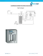
Страница 35: ...Ecostream Manual Page 35 Revision 11 13 2020 ECOSTREAM COUNTER TOP WATER FLOW DIAGRAM...

Страница 36: ...Ecostream Manual Page 36 Revision 11 13 2020 ECOSTREAM TOWER WATER FLOW DIAGRAM...

Страница 37: ...crew under the decal at the rear of the unit Remove the red portion of the Cold Tank Temperature label to access the adjustment screw The factory set point is 41 F and is indicated by the dot on sheet...

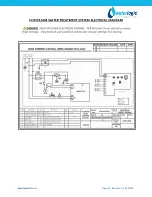
Страница 38: ...Revision 11 13 2020 ECOSTREAM WATER TREATMENT SYSTEM ELECTRICAL DIAGRAM DANGER HIGH VOLTAGE ELECTRICAL HAZARD PCB Printed Circuit Board contains High Voltage Only trained and qualified technicians sho...

Страница 39: ...uipment Rubber or Nitrile Safety Gloves and Protective Eyewear Phillips Screwdriver Temperature Gage Water Pitcher or Container to collect water from the faucet 5 gallon container or drain basin Sanit...

Страница 40: ...oves and eye protection when using chemicals Refer to Material Safety Data Sheet for specific requirements of each chemical product Take all necessary precautions to prevent sanitizer from contacting...

Страница 41: ...OFF position while the hot tank is empty Damage could occur within one minute and the overload high limit will require manual reset if heater is turned on with an empty hot tank Fill the Cold Circuit...

Страница 42: ...Test 19 Switch Red Compressor Heater to I ON position Always ensure tanks are full of water before turning on the heater or the overload high limit will open and require manual reset If the wire conde...

Страница 43: ...sable Cold and Hot Tanks 1 Turn off the Red Heater and Compressor Power Switch O OFF to disable the heater and compressor 2 Dispense 2 liters 1 2 Gallon of water through the hot tank to cool the water...

Страница 44: ...and Compressor Power Switch is turned off the heater will not energize and heat the incoming tap water Following this precaution prevents exposing personnel and equipment drains catch basin etc to sca...

Страница 45: ...e tubing into the Line Bulkhead fitting at back of the ECOSTREAM Water Treatment System to allow water to drain 6 Depress Cold Water Dispense Button until all Cold Water has drained from the ECOSTREAM...

Страница 46: ...pose to direct sunlight heat sources or ambient air temperature above 38 C 100 F or below 2 C 35 F Install indoors and keep unit away from excessive humidity Never expose to freezing temperatures Ensu...

Страница 47: ...ntinuous flow of water is obtained Once a continuous flow is obtained release the dispensing button Cold tank is now full 5 Fill the Hot Tank Hold a container under the dispensing faucet Press the Hot...

Страница 48: ...m has reached its Hot Temp Set Point the heater will cycle off When the ECOSTREAM Water Treatment System has reached its Cold Temp Set Point Temperature the compressor will cycle off 12 Once the ECOST...

Страница 49: ...ver defaulted to ON If no buttons are pressed on the front panel for 3 hours the Ecostream will enter sleep mode and power to the heater will be shut down The cold water compressor will remain active...

Страница 50: ...T BE MADE WITH THE POWER OFF OR THE POWER MUST BE CYCLED AFTER THE SETTING CHANGE IF NOT DONE THE CHANGE WILL NOT BE RECOGNIZED Note the DIP switches on the front display pcb the one mounted to the ba...

Страница 51: ...t and the Red LED on the Front won t light Possible Reason Solution Circuit Breaker Check the Circuit Breaker Fuse is Blown Replace Fuse Defective Loose Power Cord Check that power cord is properly pl...

Страница 52: ...il of any obstructions or dust Reduction of airflow into unit Make sure unit is not under minimum ventilation requirements 2 to 4 inches Compressor is running very hot Low or lost refrigerant Refriger...

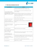
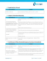
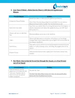
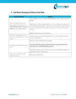
Страница 53: ...rvice Flow is 1 89 Liters 0 5 gallons per Minute 7 Hot Water Intermittently Forced Through the Faucet or a Dual Stream Out of the Faucet 8 Hot Water coming out of both the Faucet and the Vent Hole 9 H...

Страница 54: ...l method of verification is to turn off water to unit and press the dispense button Does the solenoid open without water pressure to the unit Listen for solenoid to activate not button click Adjust wa...

Страница 55: ...Open the water supply valve The unit is not properly plugged into electrical outlet Check electrical outlet connection or for blown circuit breaker Red Heater and Compressor Switch on unit is in the o...

Страница 56: ...Front Dispensing PCB or Solenoid Connector Check that they are connected properly and tightened Solenoid If both the Water Pressure and PCB have been ruled out then it is the Solenoid Replace Solenoi...

Страница 57: ...he feed line Filters Filters with high pressure drop due to fouling or just by design Change filters more frequently or go to higher micron size filter for local water conditions Restrictions Flow pat...

Страница 58: ...pen without water pressure to the unit Listen for solenoid to activate not button click Adjust water pressure to 40 60 psi Improper tubing attachment from the tank to faucet or vice versa Verify tubin...

Страница 59: ...always full by allowing more water in than out There is a small hole in the side of the tank outlet tube that allows air and water to pass into the vent chamber as it is heated Water in the vent cham...

Страница 60: ...ater to unit and press the dispense button Does the solenoid open without water pressure to the unit Listen for solenoid to activate not button click Adjust water pressure to 40 60 psi Hot or Cold sol...

Страница 61: ...ionality Red Heater and Compressor Switch on unit is off Turn Red Heater and Compressor Switch on I ON Loose connection s on the Display PCB Turn power off unplug the unit and visually inspect solenoi...

Страница 62: ...nk has an outlet restrictor to ensure the tanks remain full of water and water is controlled as it is released to the faucet The inlet solenoid controls flow into the tanks The tanks will depressurize...

Страница 63: ...cold water Cold tank capacity is 4 liters for Tower and 2 liters for Counter Top Wait for cold tank to chill water to temperature prior to dispensing more cold water A greater capacity of Waterlogic W...

Страница 64: ...k is dry heated turned on without water in it The ECOSTREAM Water Treatment does NOT have Extra Hot capability and the maximum hot temperature is 87 C 189 F It typically takes 10 minutes for the 500W...

Страница 65: ...ater element for approximately 26 OHM s resistance Hot Tank must be empty if you are checking for continuity Replace Hot Tank as necessary Loose or improperly connected wire s to the Heating Element H...

Отзывы: